Hydraulic clutch and transmission device provided with the same

a transmission device and hydraulic clutch technology, applied in the direction of fluid actuated clutches, clutches, non-mechanical actuated clutches, etc., can solve the problems of increasing the axial length of the transmission device, hindering the efforts to make the hydraulic clutch and the transmission device provided with the hydraulic clutch more compact, and increasing the number of parts. , to achieve the effect of simplifying the structur

Active Publication Date: 2014-08-05
AISIN AW CO LTD
View PDF11 Cites 4 Cited by
  • Summary
  • Abstract
  • Description
  • Claims
  • Application Information

AI Technical Summary

Benefits of technology

[0004]However, in the transmission device according to the related art described above, the radially-extending first clearance that serves as the oil passage to the hydraulic servo and the radially-extending second clearance that serves as the oil passage to the cancel oil chamber of the first clutch are arranged parallel in the axial direction. This increases the axial length of the transmission device, and hinders efforts to make a hydraulic clutch and a transmission device provided with the hydraulic clutch more compact. In addition, forming the first clearance that serves as the oil passage to the hydraulic servo of the first clutch requires members other than the structural members of the first clutch (the clutch drum of the second clutch in the transmission device of JP 2009-30654 A), which may increase the number of parts and result in a more complicated and larger device overall.
[0005]The present invention provides a hydraulic clutch with a compact and simple configuration, and a transmission device provided with the hydraulic clutch.
[0008]In the hydraulic clutch, the side wall portion of the clutch drum is formed with the first oil passage that radially extends and is in communication with the engagement side oil chamber, and the second oil passage that radially extends and is in communication with the cancel oil chamber. In addition, one of the first and second oil passages is at least partially included in the range of the axial width of the other of the first and second oil passages. Thus, the first oil passage for supplying oil to the engagement side oil chamber and the second oil passage for supplying oil to the cancel oil chamber are formed on substantially the same plane within the side wall portion of the clutch drum. Therefore, the first and second oil passages are not formed parallel in the axial direction, and an increase in the axial length of the hydraulic clutch can be suppressed. In addition, the first and second oil passages are both formed within the side wall portion of the clutch drum. There is thus no need to use a separate member for forming the oil passages. Moreover, an increase in the number of parts can be suppressed and the hydraulic clutch can have a more simple and downsized configuration. Consequently, according to the present invention, a hydraulic clutch with a compact and simple configuration can be achieved.
[0010]Further, the first and second oil passages may each be formed from a hole portion that is formed penetrating radially inward from an outer periphery of the side wall portion of the clutch drum, and an opening portion of the hole portion positioned on an outer circumferential side of the side wall portion may be closed by a lid element. Thus, the first and second oil passages can be easily formed.
[0013]The clutch drum may include an inner cylinder portion that axially extends from an inner circumferential portion of the side wall portion, and the inner cylinder portion may be fitted with a cylindrical sleeve that is rotatably supported by a fixed member of the transmission device such that the sleeve rotates together with the inner cylinder portion. In addition, the first oil passage may be in communication with a first supply passage formed in the fixed member through a first oil hole formed in the sleeve and a first relay oil passage formed in the inner cylinder portion, and the second oil passage may be in communication with a second supply passage formed in the fixed member through a second oil hole formed in the sleeve and a second relay oil passage formed in the inner cylinder portion. Thus, even if the first and second supply passages formed in the fixed member of the transmission device have a simplified structure, the first and second oil passages can easily be in respective communication with the first and second supply passages.

Problems solved by technology

This increases the axial length of the transmission device, and hinders efforts to make a hydraulic clutch and a transmission device provided with the hydraulic clutch more compact.
In addition, forming the first clearance that serves as the oil passage to the hydraulic servo of the first clutch requires members other than the structural members of the first clutch (the clutch drum of the second clutch in the transmission device of JP 2009-30654 A), which may increase the number of parts and result in a more complicated and larger device overall.

Method used


Image

  • Hydraulic clutch and transmission device provided with the same
  • Hydraulic clutch and transmission device provided with the same
  • Hydraulic clutch and transmission device provided with the same

Examples


Embodiment Construction

[0021]Next, an embodiment of the present invention will be described.

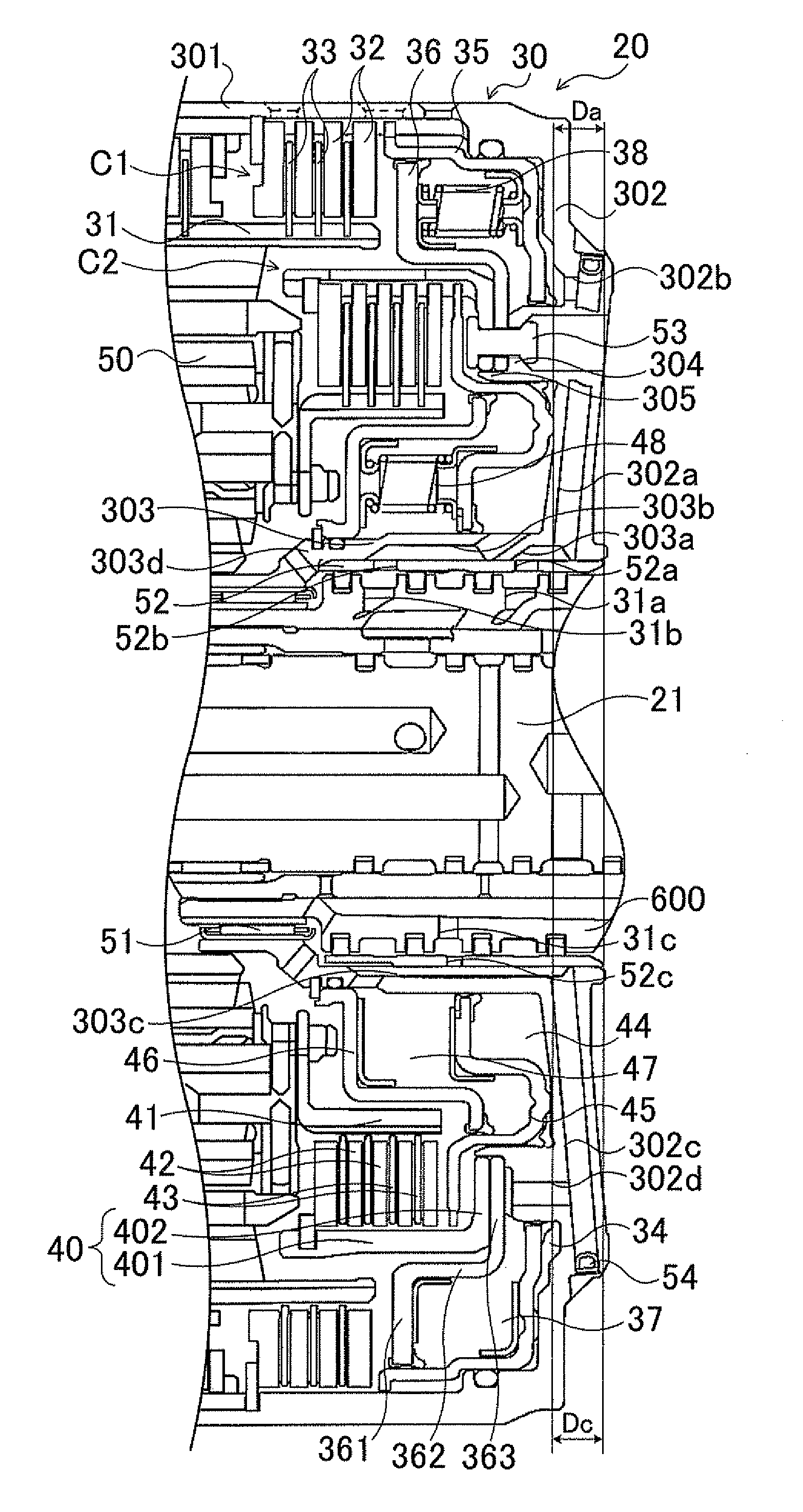
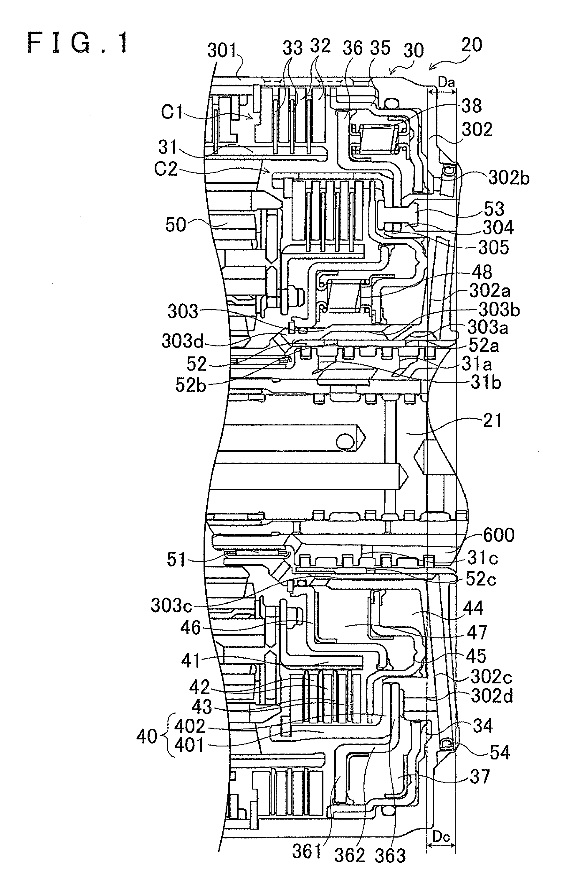
[0022]FIG. 1 is an enlarged sectional view that shows an essential portion of an automatic transmission 20 provided with clutches C1 and C2 according to an embodiment of the present invention. The automatic transmission 20 according to the embodiment is configured as a stepped transmission and mounted in a vehicle. As shown in FIG. 1, the automatic transmission 20 includes an input shaft 21, as well as the clutches C1 and C2, a plurality of other clutches and brakes (not shown), and a planetary gear mechanism 50 for changing a power transmission path from the input shaft 21 to an output shaft (not shown). The clutches C1 and C2, the plurality of other clutches and brakes, and the planetary gear mechanism 50 are accommodated inside a transmission case (not shown). Note that the input shaft 21 of the automatic transmission 20 is connected to a crankshaft of an engine through a torque converter or the like, and the ou...


PUM


Abstract

A hydraulic clutch including a clutch drum with an outer cylinder fitted with a plurality of clutch plates and a side wall; a clutch piston that defines together with the clutch drum an engagement oil chamber, and moves in an axial direction to press the clutch plates by hydraulic pressure supplied to the engagement oil chamber; and a cancel plate that defines together with the clutch piston a cancel oil chamber that cancels centrifugal hydraulic pressure. The side wall of the clutch drum is formed with a first oil passage that radially extends and is in communication with the engagement oil chamber, and a second oil passage that radially extends and is in communication with the cancel oil chamber. One of the first and second oil passages is at least partially included in a range of an axial width of the other of the first and second oil passages.

Description

INCORPORATION BY REFERENCE[0001]The disclosure of Japanese Patent Application Nos. 2011-074722 and 2011-231179 filed on Mar. 30, 2011 and Oct. 20, 2011, respectively, including the specifications, drawings and abstracts are incorporated herein by reference in their entirety.BACKGROUND OF THE INVENTION[0002]The present invention relates to a hydraulic clutch including a clutch drum that is fitted with a plurality of clutch plates; a clutch piston that together with the clutch drum defines an engagement side oil chamber; and a cancel plate that together with the clutch piston defines a cancel oil chamber for canceling centrifugal hydraulic pressure, and also relates to a transmission device provided with the hydraulic clutch.DESCRIPTION OF THE RELATED ART[0003]A past proposed example of a transmission device can transmit power applied to an input shaft to an output shaft, and change a speed ratio to a plurality of stages by switching the engagement states of a plurality of hydraulic c...

Claims


Application Information

Patent Timeline
Patent Type & Authority Patents(United States)
IPC IPC(8): F16D25/10F16D13/68F16D48/02F16D25/0638F16D25/12F16D21/06
CPCF16D21/06F16D25/10F16D25/0638F16D13/683F16D25/12F16D2048/029
Inventor KASUYA, SATORUKATOU, HIROSHIISHII, TAKUYATOKUNAGA, NORIHIROTAMABAYASHI, KENTA
Owner AISIN AW CO LTD
Why Eureka
Try Eureka