
Sub-motor-threshold stimulation of deep brain targets using transcranial magnetic stimulation

a transcranial magnetic stimulation and sub-motor technology, applied in magnetotherapy, magnetotherapy using coils/electromagnets, magnetotherapy, etc., can solve the problems of unexpective effective sub-mt stimulation and achieve the effect of easier fire and greater probability of excitation

Active Publication Date: 2014-08-05
BRAINSWAY
View PDF156 Cites 29 Cited by
  • Summary
  • Abstract
  • Description
  • Claims
  • Application Information

AI Technical Summary

Benefits of technology

This approach unexpectedly achieves effective modulation of deep brain targets at significantly lower power levels than previously thought necessary, as demonstrated by increased blood perfusion and pain level correlations in PET scans, indicating successful stimulation without excessive activation of superficial regions.

Problems solved by technology

In general, the sub-MT stimulation described here is unexpectively effective, despite being sub-MT at the deep-brain target.
Interconnected nerve tracts such as the cingulate and other tract structures may thereby capture more power / signal from the stimulation, and result in a greater probability of excitation.

Method used


Image

  • Sub-motor-threshold stimulation of deep brain targets using transcranial magnetic stimulation
  • Sub-motor-threshold stimulation of deep brain targets using transcranial magnetic stimulation
  • Sub-motor-threshold stimulation of deep brain targets using transcranial magnetic stimulation

Examples


Embodiment Construction

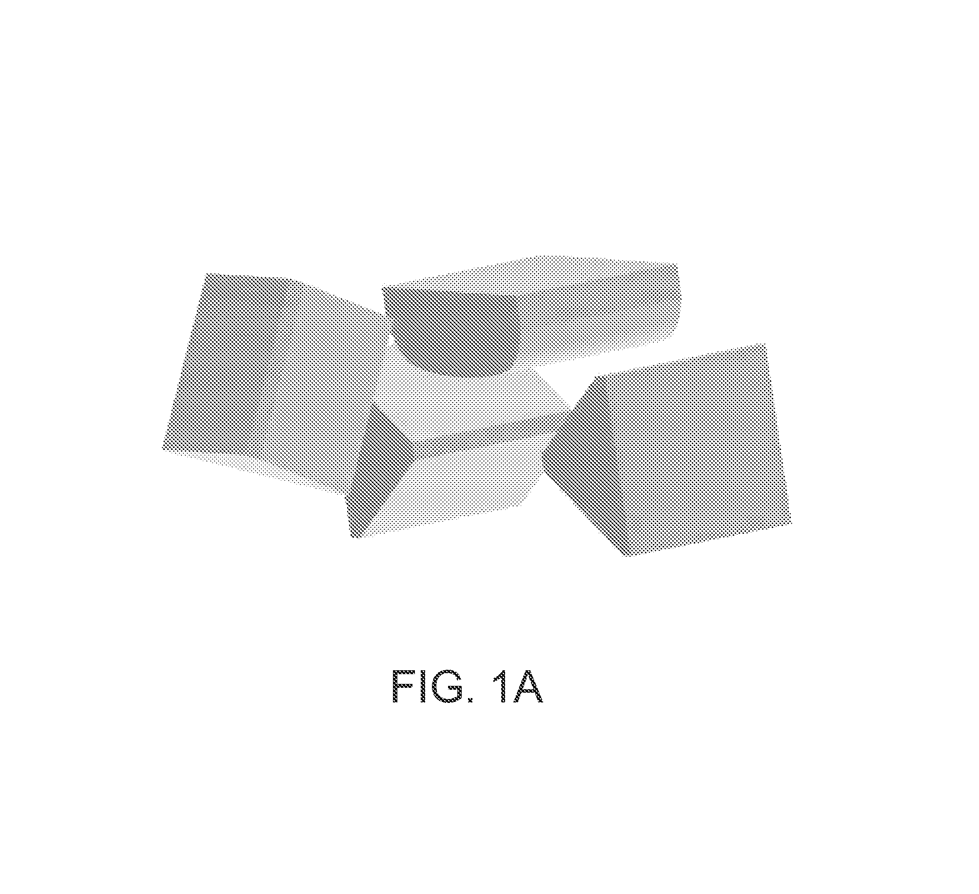
[0023]One variation of an experimental set-up is illustrated in FIG. 1A. FIG. 1A illustrates a TMS system including four TMS electromagnets. In FIG. 1A, the CAD model illustrates an arrangement of magnets which may be referred to as a “diamond array.” The subject's head and any electromagnet coil fixation device are not shown in this figure. These four TMS electromagnets may be connected to a scaffold, gantry, or other fixation device. In FIG. 1A, the center, top TMS electromagnet is a swept-wing coil and the two lateral coils are V-Coils in the same vertical plane. A third V-Coil is located anteriorly, swinging down and configured to touch the subject's forehead.

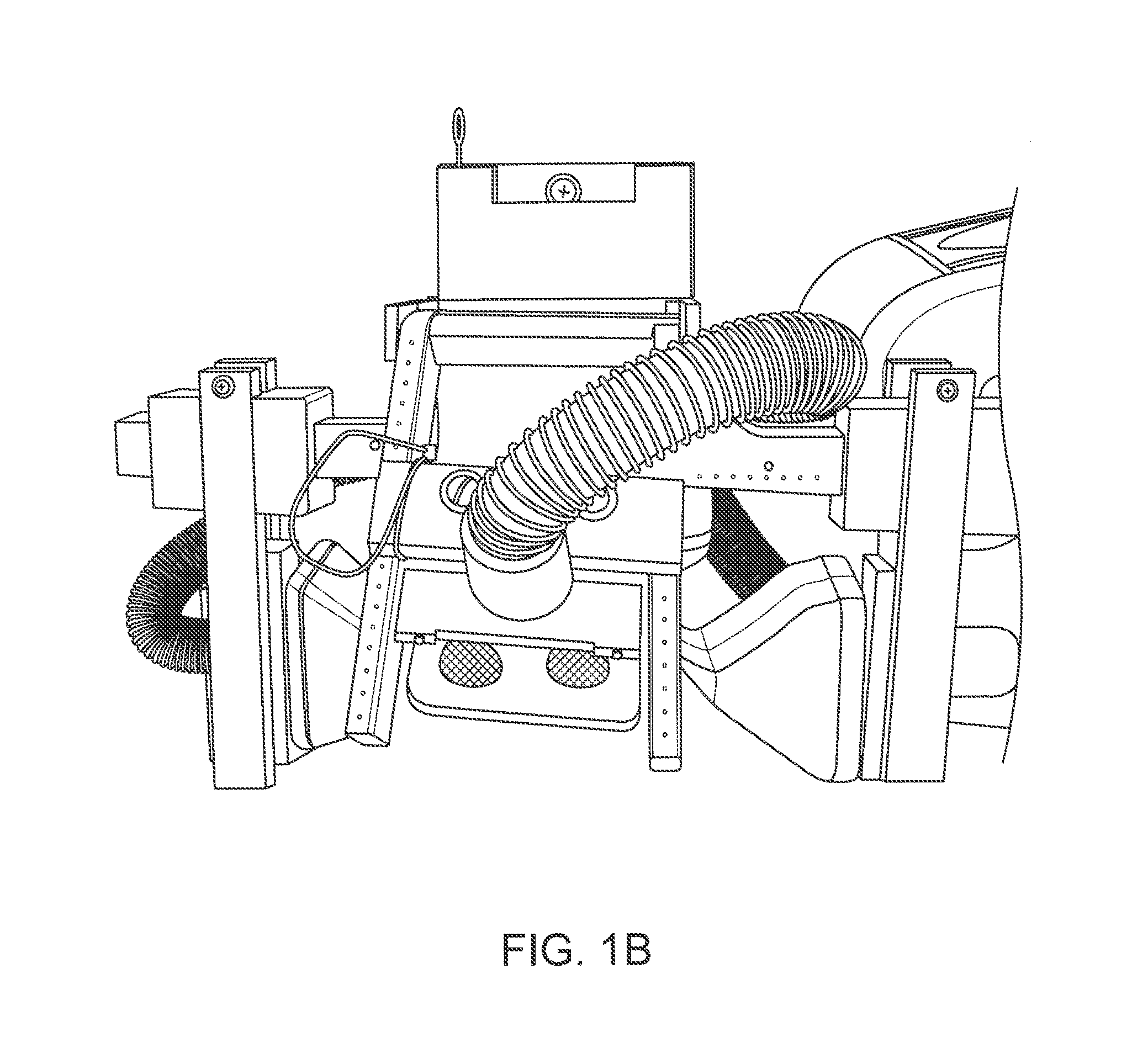
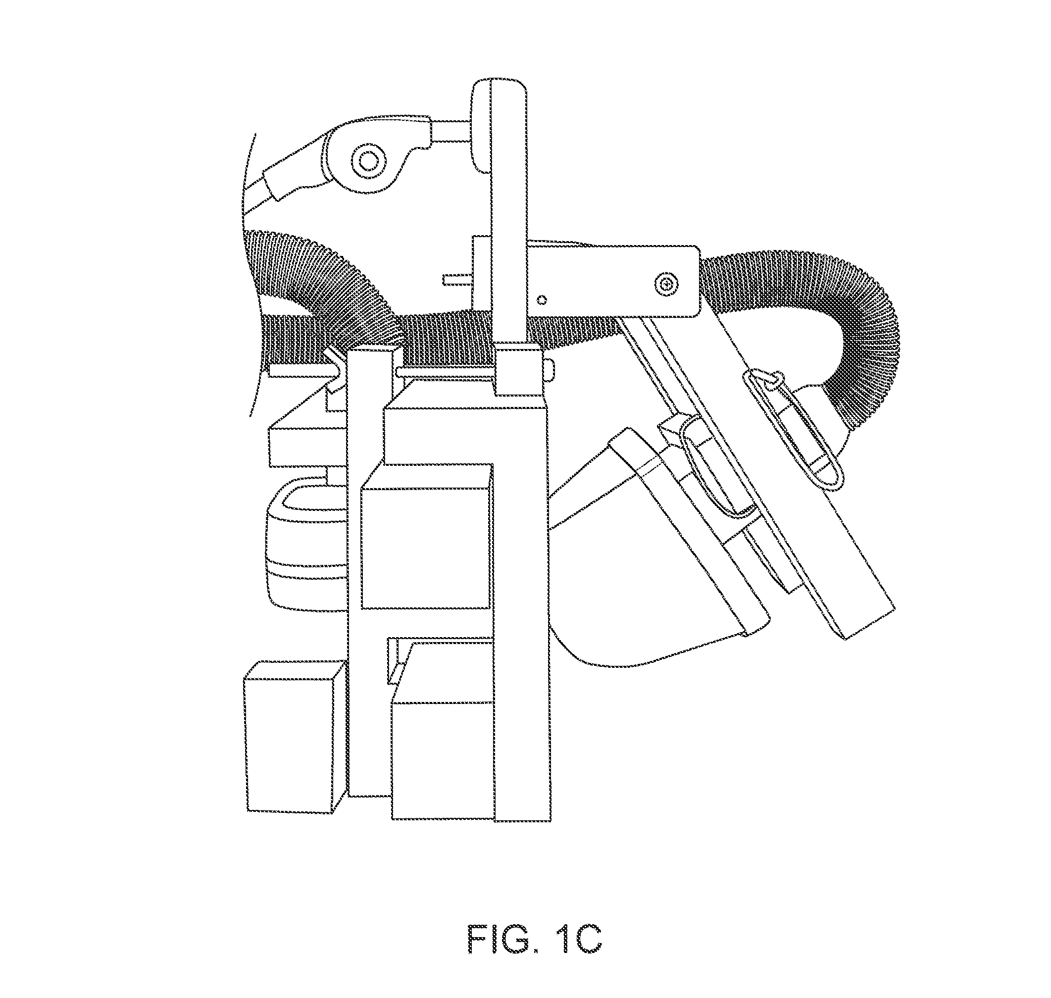
[0024]FIGS. 1B to 1C illustrate a system such as the one shown in FIG. 1A. For example, FIG. 1B shows a front view of such a system and FIG. 1C shows a side view. FIG. 1D shows a diamond-array configuration of a TMS system relative to standard EEG placement landmarks. The centers of the electromagnets are located at the lan...


PUM


Abstract

Systems and methods for modulating deep brain target regions using an array of TMS electromagnets, wherein each TMS electromagnet stimulates the target at a level that is below motor threshold (MT). Neurological disorders (or disorders having neurological effects) may be treated by sub-MT stimulation of deep-brain targets from an array of TMS electromagnets.

Description

CROSS REFERENCE TO RELATED APPLICATIONS[0001]This patent application claims priority to provisional patent application Ser. No. 61 / 254,964, filed on Oct. 26, 2009, titled “SUB-MOTOR-THRESHOLD STIMULATION OF DEEP BRAIN TARGETS USING TRANSCRANIAL MAGNETIC STIMULATION,” which is herein incorporated by reference in its entirety.[0002]This patent application may be related to pending PCT application PCT / 2008 / 073751, filed on Aug. 20, 2008, which claims priority to U.S. Provisional Patent Application Ser. No. 60 / 956,920, filed on Aug. 20, 2007, U.S. Provisional Patent Application Ser. No. 60 / 970,958, filed on Sep. 9, 2007, and U.S. Provisional Patent Application Ser. No. 61 / 077,488, filed on Jul. 2, 2008. This patent application may also be related to PCT application PCT / US2008 / 075575 (WO 2009 / 033144), filed on Sep. 8, 2008, which claims priority to U.S. Provisional Patent Application Ser. Nos. 60 / 970,534, filed Sep. 7, 2007; 60 / 970,532, filed Sep. 7, 2007; and 60 / 975,177, filed Sep. 26, ...

Claims


Application Information

Patent Timeline
Patent Type & Authority Patents(United States)
IPC IPC(8): A61N2/02
CPCA61N2/004A61N2/02
Inventor SCHNEIDER, M. BRETMISHELEVICH, DAVID J.
Owner BRAINSWAY
Learn More