Multi-machine mail sorting system

a multi-machine, mail sorting technology, applied in sorting, thin material processing, instruments, etc., can solve the problems of increasing the likelihood of contention between mail pieces, and achieve the highest system throughput, speed up or slow down the movement of a selected mail piece, and minimize the number of mail pieces

Inactive Publication Date: 2014-08-05
SIEMENS LOGISTICS LLC
View PDF19 Cites 3 Cited by
  • Summary
  • Abstract
  • Description
  • Claims
  • Application Information

AI Technical Summary

Benefits of technology

[0009]According to preferred embodiments, the second conveyors include a plurality of gap control modules operable to speed up or slow down movement of a selected mail piece, thereby adjusting gaps between front and rear ends of a mail piece and respective front and rear ends of mail pieces ahead of and trailing the mail piece acted on by the gap control module. The control system operates the gap control modules in a manner effective to avoid collisions between a merging mail piece entering a merge and mail pieces already present in the outgoing mail stream the merging mail piece is entering.
[0010]The control system maintains lists of mail pieces in outgoing streams of mail that will be merged and between mail pieces in an incoming stream that will merge with an outgoing stream. The control system operates the gap control modules based on a release plan calculated using decision rules effective to optimize merging of the mail streams being merged. The decision rules reference and compare speed and position of a leading group of one or more mail pieces on each mail stream to be merged, and are applied hierarchically in a manner that promotes the highest system throughput and minimizes the number of mail pieces that must be rejected (diverted to refeed) due to conflicts between mail pieces attempting to merge into the same outgoing stream.
[0011]The first, second and third conveyors are preferably pinch belt conveyors, and each gap control module comprises a segment of pinch belt operable by the control system at a different speed from portions of the second conveyor adjoining the gap control module. In general, a conveyor for purposes of the present invention is a mechanical system that can convey a singulated stream of mail pieces while maintaining gap spacing between mail pieces being conveyed. The merge section includes a plurality of gap control modules operable to speed up or slow down movement of a selected mail piece upstream from a merge, wand the control system operates the gap control modules in a manner as effective as possible to avoid collisions between mail pieces in different streams.
[0012]The present invention represents an improvement over the system as described in the '606 system because it is able to accomplish routing without using a conveyor crossover function. This reduces the likelihood of contention between mail pieces and increases the performance by reducing the quantity of mail that must be rejected due to mail that needs to be simultaneously to the same path, so the effective overall throughput of the system is increased and the amount of mail that must be fed again is reduced.
[0016](c) speeding up and slowing down one or more selected mail pieces on one or both of the conveyors using gap control modules forming part of the pinch belt conveyors in a manner effective to avoid collisions between mail pieces at the merge. To operate the conveyors at high speed the method also preferably includes steps of:

Problems solved by technology

Such a crossover function increases the likelihood of contention between mail pieces at the intersection of the conveyor paths.

Method used


Image

  • Multi-machine mail sorting system
  • Multi-machine mail sorting system
  • Multi-machine mail sorting system

Examples


Embodiment Construction

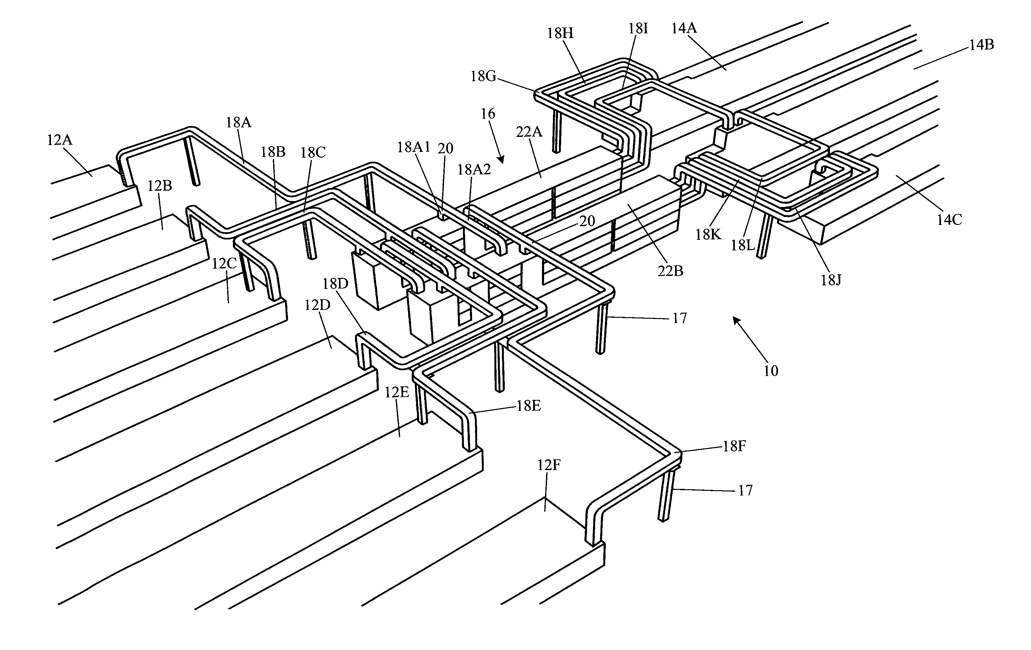
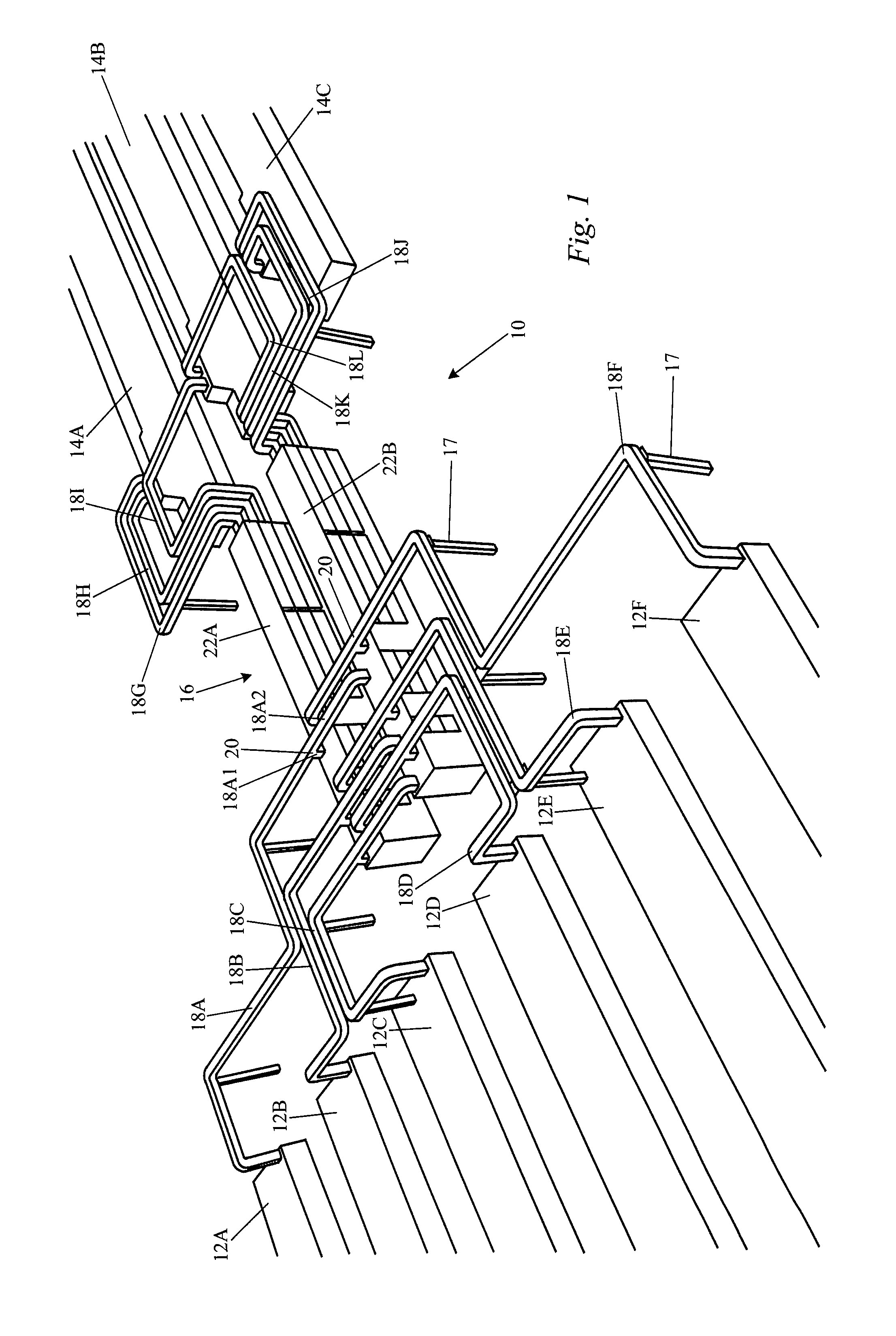
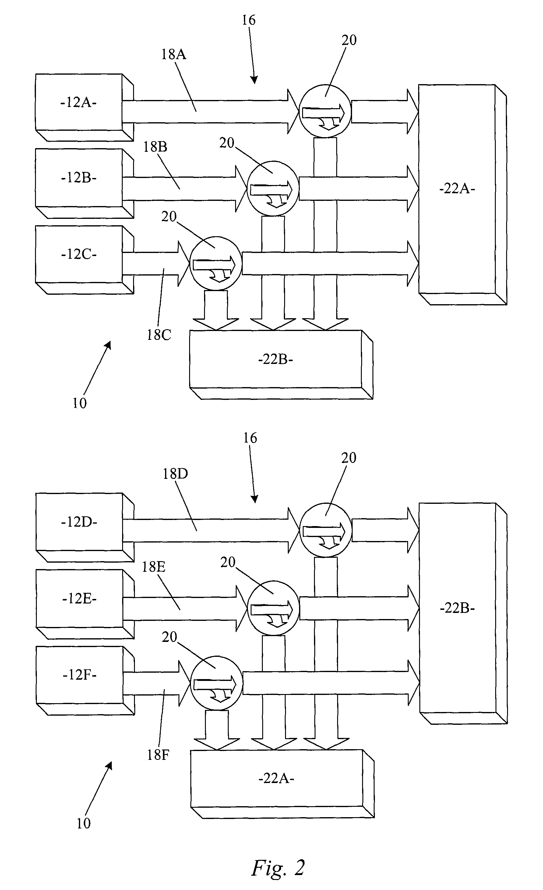
[0033]Referring to FIGS. 1-4, an embodiment of a sorting system 10 according to the invention interconnects eight input sections 12 to up to four output sections (stacker lines) 14 by means of a switch network 16. This results in a labor savings because in today's environment mail is processed on an AFCS and then taken to an outgoing primary (OGP) sort on a DBCS machine where an operator must feed the mail again. By using a switch network, the labor to queue the mail and feed it on the OGP sort is avoided. The term “switch network” as used herein refers to a set of conveyor pathways that have the ability to switch mail from any one input section 12 to any level of any stacker 14. The preferred switch network according to the present invention uses diverts and merges, but does not use cross-overs or intersections between conveyor paths, which if present limit system performance (slow it down).

[0034]An “input section according to the invention is typically the front end of a postal so...


PUM

PropertyMeasurementUnit
timeaaaaaaaaaa
lengthaaaaaaaaaa
speedaaaaaaaaaa

Abstract

A sorting system for postal mail has a plurality of input sections capable of operating in parallel, each including a feeder that takes in mail pieces one at a time and a scanner that scans each mail piece for destination indicia. The system further includes a plurality of stackers each comprising at least one row of pockets in which mail is stacked, and a routing section or switch network effective to route mail in accordance with a sort scheme from any input section to any pocket of a stacker. The routing section uses diverts and merges so that mail can be conveyed to each stacker in accordance with a sort scheme implemented by a control system.

Description

FIELD OF THE INVENTION[0001]The invention relates to mail sorting machines and processes of the type currently carried out by the U.S. Postal Service (USPS).BACKGROUND OF THE INVENTION[0002]Barnum et al. U.S. Pat. No. 6,671,577, Dec. 30, 2003, describes a system and method for directly connecting an ISS advanced facer canceler system (IAFCS) to a DBCS / OSS. Limitations of this system are described in commonly assigned Redford et al. U.S. Patent Publication No. 20050247606, Nov. 10, 2005, the contents of which are incorporated by reference herein for all purposes. Redford et al. describes a sorting system using multiple sorters operating as part of a single, multi-sorting machine unified system. The '606 system includes a plurality of input sections capable of operating in parallel, each including a feeder that takes in mail pieces one at a time and a scanner that scans each mail piece for destination indicia, a plurality of stackers each comprising at least one row of pockets, a cont...

Claims


Application Information

Patent Timeline
Patent Type & Authority Patents(United States)
IPC IPC(8): G06K9/00
CPCB07C3/00B65H29/60B65H2301/4454B65H2301/4455B65H2511/512B65H2513/42B65H2701/1916B65H2220/01B65H2220/02
Inventor HARRES, LUIZ C.BERDELLE-HILGE, PETERDICKERSON, HOMERWARREN, LELANEGER, TAMAS
Owner SIEMENS LOGISTICS LLC
Why Eureka
Try Eureka