Adjustable spring assembly for a vibrator of a bone anchored hearing aid

a technology of adjustable spring and bone anchored hearing aid, which is applied in the direction of deaf-aid sets, electric devices, etc., can solve the problems of poor production yield and mismatch to the firmware of the hearing aid, and achieve the effects of preventing spring assembly distortion, ensuring the spring rate of the vibrator, and robust attachment of the coupling

Active Publication Date: 2014-08-05
OTICON MEDICAL
View PDF10 Cites 5 Cited by
  • Summary
  • Abstract
  • Description
  • Claims
  • Application Information

AI Technical Summary

Benefits of technology

[0009]With a spring assembly according to the invention, by adjusting the spring rate of the suspension spring, a peak frequency mismatch of the vibrator can be easily compensated by moving the peak frequency into a required interval. The peak frequency of a vibrator can be moved without having to disassemble the vibrator or to replace parts. The adjustable spring assembly can advantageously be used for producing vibrators with different frequency characteristics that are made of the same part, resulting in the possibility to manufacture bone anchored hearing aids that can deliver more gain in the low or high frequency range using the same parts.
[0011]In a preferred embodiment the suspension spring is designed as a planar spring. The first end of the suspension spring is located in a peripheral, the second end in a center region of a plane of the spring. An axis of displacement is defined perpendicular to the plane and extending through the center region. Being designed as a planar spring, the suspension spring allows for flat—thus inconspicuous—design of the vibrator.
[0016]To improve support of the adjusting means and to provide for rotational guidance, the spring assembly can comprise an outer spacer disposed between the base plate and the cover plate in a sandwiched manner. The outer spacer and the adjusting means can lie in the same plane, wherein the outer spacer is designed complementary to an outer perimeter of the adjusting means.
[0017]In a further embodiment, to prevent distortion of the spring assembly and to allow for a robust attachment of the coupling, the spring assembly comprises a center spacer disposed between the base plate and the cover plate in a sandwiched manner. The center spacer is disposed within the center hole of the adjusting means. The center spacer can reside within the center hole of the adjusting means contactless to the adjusting means. The center spacer can be laser welded to the base plate and / or the cover plate.
[0018]In a further preferred embodiment the spring assembly is attached to the mass via a fastening means. The fastening means can be provided as screws. Slightly loosening the fastening means allows for adjusting the spring constant. Retightening the fastening means prevents a self-adjustment of the spring constant when the vibrator is in operation. When the fastening means are retightened, the adjusting means is squeezed tight between the base plate and the cover plate. This embodiment allows for an even more secure adjustment of the spring rate of the vibrator.
[0019]To provide an optimal stress distribution and to facilitate an accurate assembling of the spring assembly as well as the vibrator, the base plate and the cover plate can be of square shape. The cover plate and / or the base plate can each comprise four slots in proximity to respective corners of the square. The respective slots can be equidistantly curved around the second end. The adjusting means can comprise four pads. The pads comprised by the adjusting means can firmly protrude from one plane of the adjusting means against the cover plate and from the other plane against the base plate.

Problems solved by technology

It has been observed by the inventors that due to manufacturing tolerances in the suspension spring, the mass and / or the circuit electromagnetically driving the mass, the peak frequency of the vibrator may lie well outside a desired interval, resulting in a mismatch to the hearing aid's firmware and consequently to a poor production yield.

Method used


Image

  • Adjustable spring assembly for a vibrator of a bone anchored hearing aid
  • Adjustable spring assembly for a vibrator of a bone anchored hearing aid
  • Adjustable spring assembly for a vibrator of a bone anchored hearing aid

Examples


Embodiment Construction

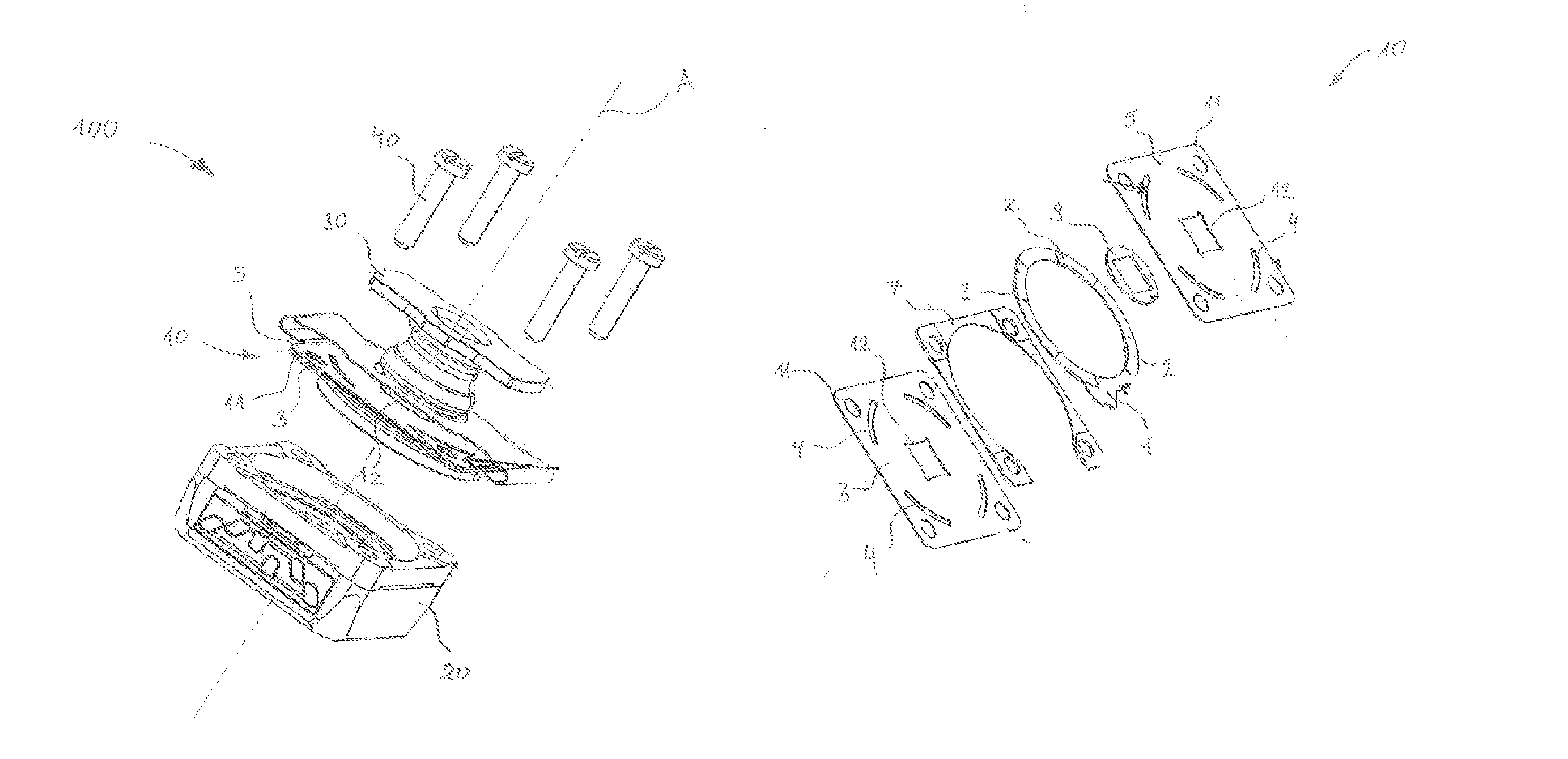
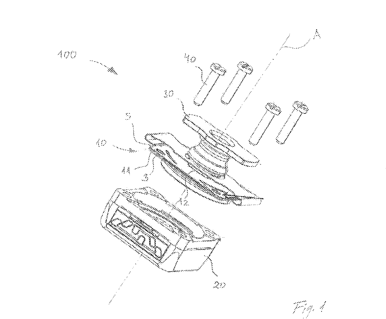
[0030]A vibrator 100 in FIG. 1 comprises a spring assembly 10, a mass 20, a coupling 30 attachable to a user's skull bone 101 (see FIG. 6) and a fastening means 40. The skull bone attachment could well be a screw 102 or similar bone anchor as shown in FIG. 6, which passes through the skin 103. The fastening means 40, which is provided as four screws, attaches the spring assembly 10 to the mass 20.

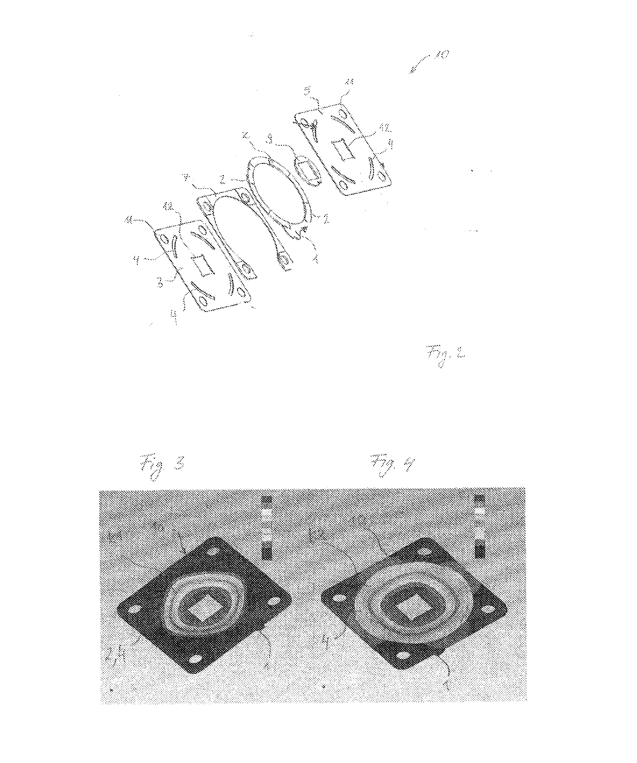
[0031]The spring assembly 10 comprises a suspension spring designed as a planar spring comprised of a base plate 3 and a cover plate 5. Base plate 3 and a cover plate 5 are of square shape and congruent to each other. Base plate 3 and cover plate 5 have a first end 11, which is designed as respective four bores, located in a peripheral region and a second end 12 located in a center region of their planes. The first end 11 is immovably connected to the mass 20, the second end 12 immovably connected to the coupling 30.

[0032]The base plate 3 and the cover plate 5 may be round or rounded in sha...


PUM


Abstract

Spring assembly as part of a vibrator for a bone anchored hearing aid, wherein the spring assembly comprises a suspension spring having a first end immovably connected to a mass of the vibrator and a second end immovably connected to a coupling attachable to a user's skull bone and comprised by the vibrator, wherein the spring assembly comprises an adjusting means adapted to adjust a spring rate of the suspension spring between a first spring rate and a second spring rate, the first rate being higher than the second rate, so as to move a resonance peak of the vibrator.

Description

CROSS-REFERENCE TO RELATED APPLICATIONS[0001]This nonprovisional application claims the benefit of U.S. Provisional Application No. 61 / 577,115 filed on Dec. 19, 2011 and to Patent Application No. 11194307.2 filed on Dec. 19, 2011 in Europe. The entire contents of all of the above applications is hereby incorporated by reference.BACKGROUND OF THE INVENTION[0002]The invention is related to the field of bone anchored hearing aids, more specifically to a spring assembly comprising a suspension spring for use in a vibrator of a bone anchored hearing aid.[0003]A vibrator of a bone anchored hearing aid transduces an electrical auditory signal into a mechanical stimulus perceivable by a user via bone conduction. The vibrator is a resonant system formed by an electromagnetically driven mass suspended by a suspension spring. Connected to the suspension spring is a coupling attachable to a user's skull bone. Depending on chosen weight of the mass and spring rate of the suspension spring, the v...

Claims


Application Information

Patent Timeline
Patent Type & Authority Patents(United States)
IPC IPC(8): H04R25/00
CPCH04R25/606
Inventor JINTON, LARS
Owner OTICON MEDICAL
Why Eureka
Try Eureka