Flow monitored particle sensor

a technology of flow monitoring and particle sensor, which is applied in the direction of liquid/fluent solid measurement, volume/mass flow by differential pressure, instruments, etc., can solve the problems of inability to monitor volumetric flow rate in a low cost and accurate manner, cost hundreds of dollars per particle sensor, and sensing devices that in total cost more than one hundred dollars, so as to achieve the effect of reliable monitoring of the flow rate of sampled gas

Active Publication Date: 2014-08-12
PARTICLE MEASURING SYST
View PDF72 Cites 34 Cited by
  • Summary
  • Abstract
  • Description
  • Claims
  • Application Information

AI Technical Summary

Benefits of technology

[0005]Provided herein is a low-cost particle sensor with an accurate volumetric flow monitoring device that can reliably monitor the flow rate of sampled gas. In particular, the devices and methods provided herein are useful for identifying adverse flow events within the sensor that may otherwise remain undetected. The system presented herein provides flow monitoring in a particle sensor without the need for expensive flow or pressure sensors, and / or blowers for generating controlled flow-rates. Instead, flow may be reliably generated via a vacuum source, and flow-rate monitored as described herein.
[0006]Use of one differential pressure sensor and two absolute pressure sensors, along with algorithms based on the output of these sensors, facilitates the ability to produce a low-cost intelligent flow monitoring solution that is both accurate and inexpensive. The systems provide the capability of accurately assessing and identifying a flow condition error and, optionally, whether the flow condition error is related to a flow input obstruction (“upstream pressure loss”) or a loss in vacuum (“downstream vacuum loss”). Conventional particle sensors, in contrast, even those capable of monitoring flow-rate, do not distinguish the reason for a flow rate condition error.
[0048]In another aspect, the invention relates to sensors that are each of low-cost, thereby ensuring the particle sensor in which the sensors are incorporated remains low cost. Low cost can be defined in any number of manners ranging from functional or performance-based parameters or in terms of absolute cost. For example, a sensor that is low cost may reflect that the sensor's sensitivity, repeatability or accuracy to detect changes in pressure. For example, certain low cost sensors have a maximum accuracy of 2.5% (full scale span), whereas higher cost sensors are generally of higher sensitivity, repeatability and accuracy. Alternatively, low cost may be expressed in terms of the cost, as provided herein, of the sensors used in the particle sensor.

Problems solved by technology

Although a critical flow orifice is a very good low cost volumetric flow control device, such an orifice does not provide the capacity to monitor volumetric flow rate in a low cost and accurate manner.
Off-the-shelf flow sensors can be utilized, but cost hundreds of dollars per particle sensor.
Such internal flow-monitoring, however, also requires flow sensing devices that in total cost greater than one hundred dollars.
Such costs make the use of such devices in low cost aerosol optical particle sensors impractical.

Method used


Image

  • Flow monitored particle sensor
  • Flow monitored particle sensor
  • Flow monitored particle sensor

Examples


example 1

Critical Flow Orifice for Controlling Flow-Rate

[0061]The required critical pressure drop needed is given by the following equation.

Pv / Pa=[2 / (k+1)]k / (k-1)  (1)

[0062]Pv=Pressure on vacuum side of critical flow orifice

[0063]Pa=Pressure on upstream side of critical flow orifice

[0064]k=Gas specific heat ratio=7 / 5 for diatomic gases=1.4

[0065]Substituting 1.4 for k yields the simplified equation:

Pv / Pa=0.53  (2)

[0066]At standard conditions Pa=14.7 psi. Therefore, the required critical pressure drop at standard conditions is 7.791 psi (15.9″ Hg).

[0067]At standard conditions a critical flow orifice will maintain constant volumetric flow when the downstream vacuum level is greater than 15.9″ Hg. Under these conditions the velocity in the throat of the orifice is the speed of sound, and a further increase in the downstream vacuum level does not increase the velocity through the throat. Most prior art particle sensors utilize a knife-edge critical flow orifice. This requires the user to provide ...

example 2

Low-Cost Flow Monitoring

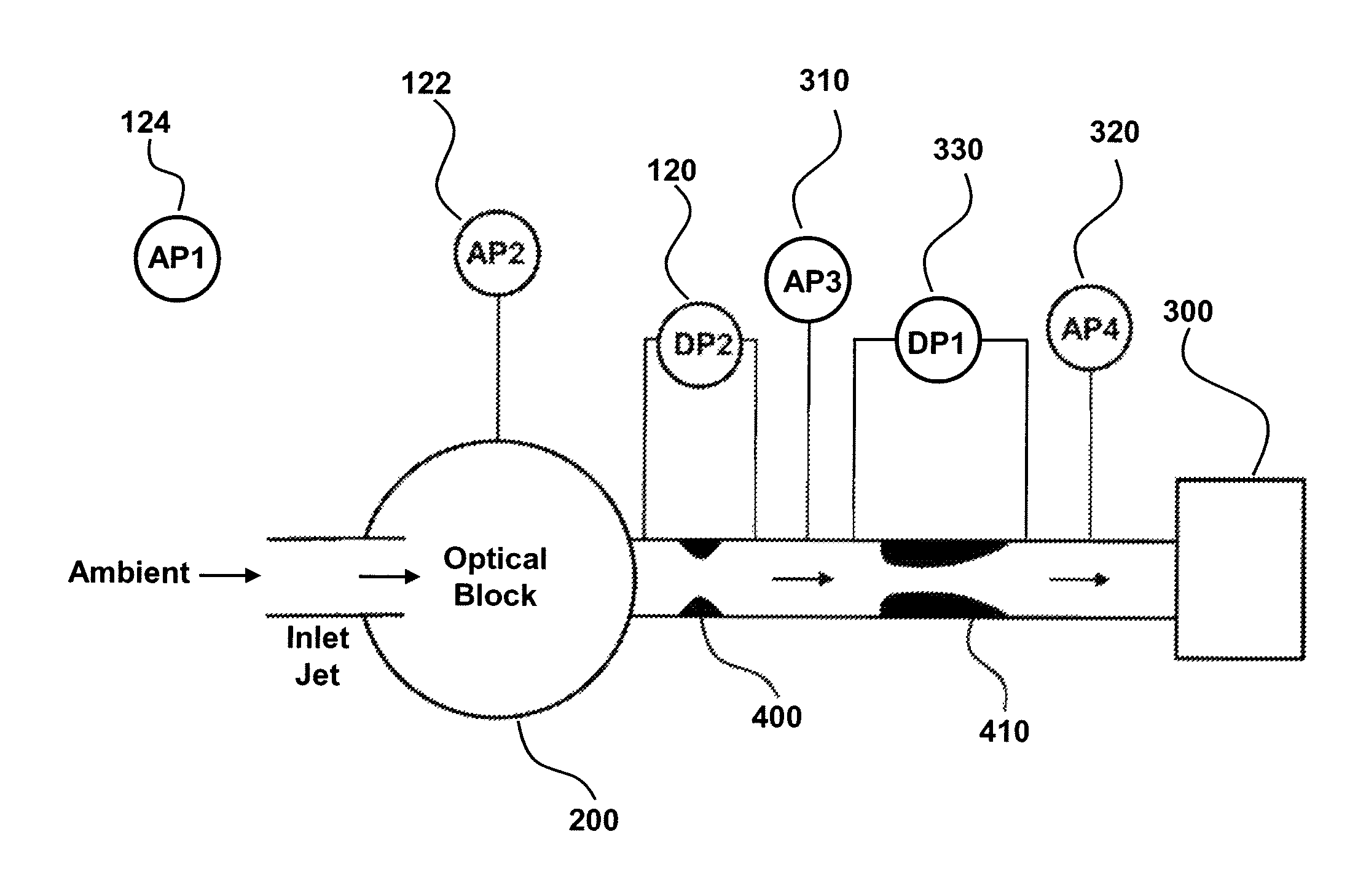
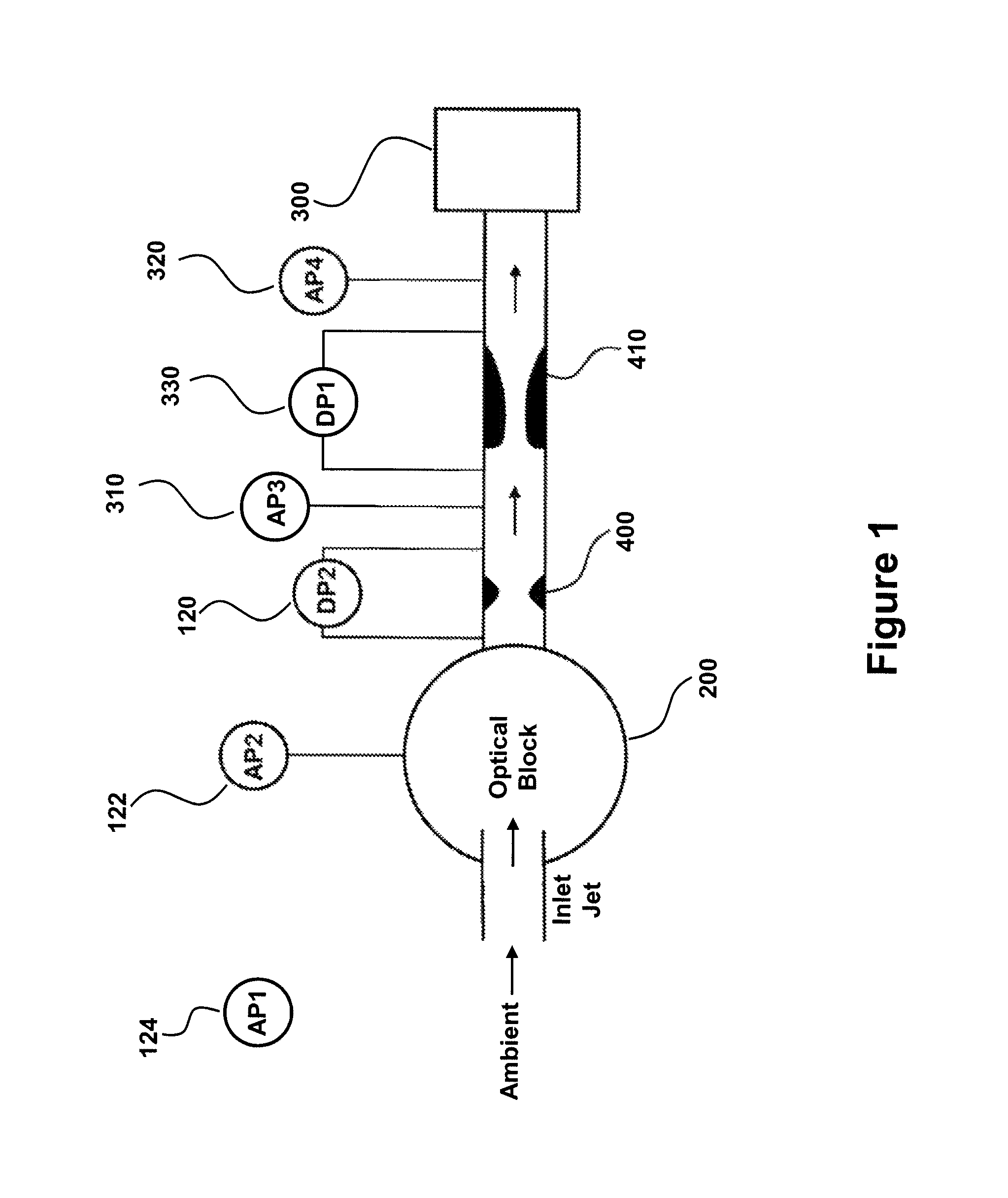
[0069]FIG. 1 details the fluidic design features of a particle sensor that may be used to intelligently monitor flow rate. The particle sensor includes an inlet jet from which ambient air is drawn from the ambient environment into the optical block 200 of the particle sensor. The optical block is the portion of the system that performs the particle detection, as particles suspended in the moving air are drawn through a laser beam and scatter light energy before exiting the optical block.

[0070]The air is drawn through a flow measurement orifice 400. The differential pressure 120 across this orifice is used to measure the flow rate through the particle sensor. This differential pressure is minimized as its pressure drop is added directly to the required pressure drop of the critical flow orifice. The air is then drawn through a venturi critical flow orifice 410 before being pulled out of the sensor by the external vacuum system 300. The critical flow orifice is...

example 3

Algorithm for Identifying Flow Condition

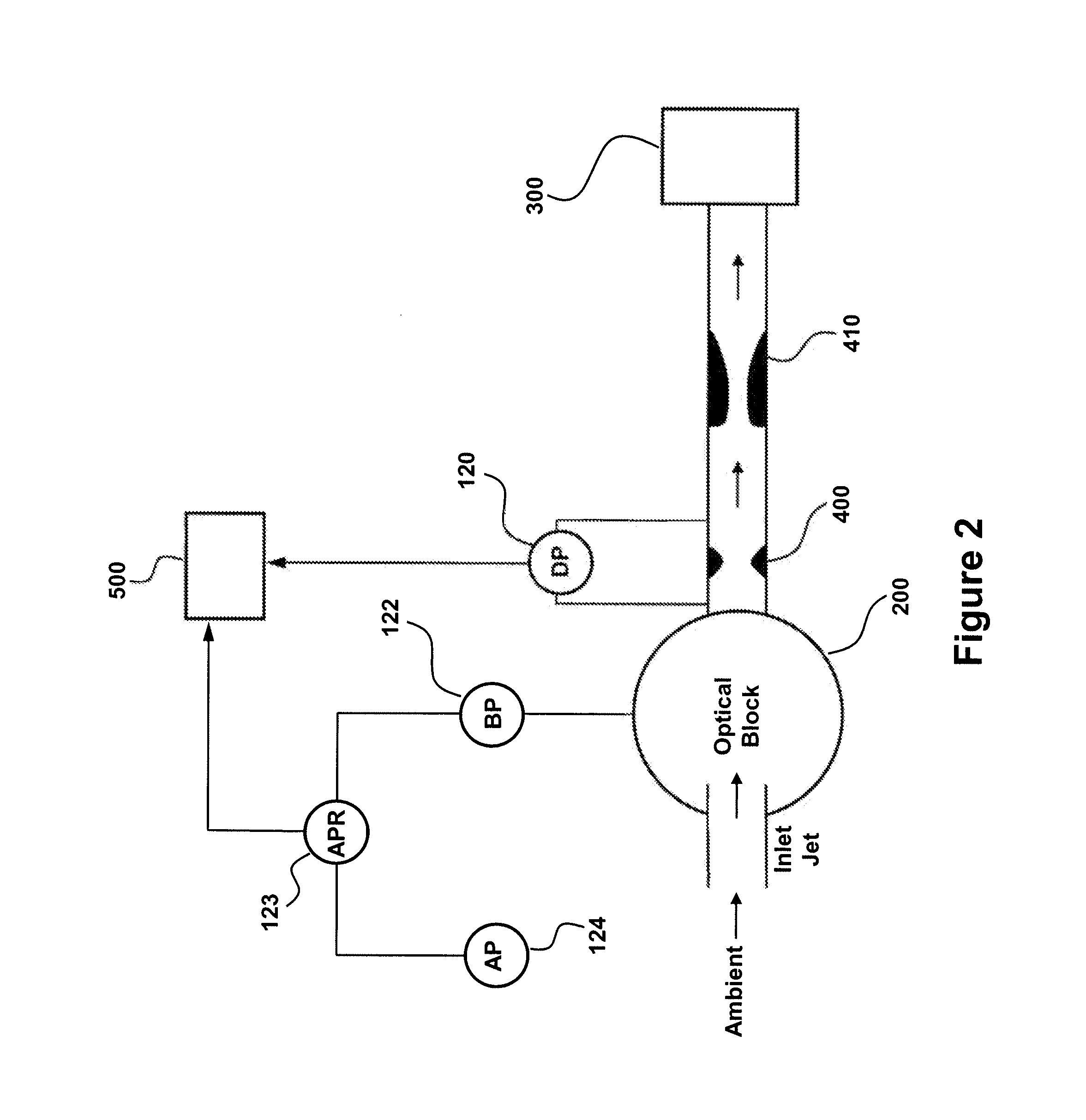
[0094]Provided is a device and method for monitoring volumetric flow rate in a particle sensor by the use of one low cost differential pressure sensor and two low cost absolute pressure sensors. The focus of this method is to produce a low cost intelligent flow monitoring solution that is both better than 10% accurate (e.g., capable of reliably detecting a 10% or greater deviation from a target flow rate) and inexpensive.

[0095]One example of a suitable differential pressure sensor 120 is a Freescale® Semiconductor MPXV5004DP. This sensor has an accuracy specification of + / −2.5% full scale, through a temperature range of + / −5° C. from calibration temperature. The flow measurement orifice in the particle sensor can be sized to operate the differential pressure sensor at near full scale.

[0096]Since the accuracy is not specified beyond a temperature range exceeding + / −5° C. C, the additional error will need to be empirically derived. A reasonable ...


PUM


Abstract

Provided are devices and methods for monitoring flow rate in aerosol particle counters. The particle sensor has a particle counter, a flow measurement orifice comprising a differential pressure sensor for measuring differential pressure (DP) across the flow measurement orifice during particle sensor operation and a critical flow orifice. A vacuum source pulls ambient gas through each of the particle counter, flow measurement orifice and critical flow orifice. An atmospheric pressure sensor measures atmospheric pressure (AP) and a bench pressure sensor measures pressure in the particle sensor (BP). The output from the sensors is used to identify a flow condition, such as by a monitor operably connected to each of the differential pressure sensor, atmospheric pressure sensor and bench pressure sensor. In this manner, deviation in flow rate from a target flow rate is readily monitored without the need for expensive sensors or other flow-controlling components.

Description

CROSS-REFERENCE TO RELATED APPLICATIONS[0001]This application is the U.S. national stage application under 35 U.S.C. §371 of International Application No. PCT / US2010 / 046438, filed Aug. 24, 2010, which claims benefit of U.S. provisional patent application 61 / 236,318 filed Aug. 24, 2009, each of which is hereby incorporated by reference to the extent it is not inconsistent with the present disclosure.BACKGROUND OF THE INVENTION[0002]Aerosol optical particle sensors are important in a number of fields. For example, the micro-contamination industry is reliant on the use of aerosol optical particle sensors to provide a quantitative assessment of contamination. Aerosol optical particle sensors are employed for point of use measurement of air-born particle contamination in clean-rooms and clean zones. Generally, these particle sensors are low cost and do not rely on internal pumps to generate the required airflow through the sensor. The particle sensors instead rely on connection to house ...

Claims


Application Information

Patent Timeline
Patent Type & Authority Patents(United States)
IPC IPC(8): G01F1/42
CPCG01N1/24G01F1/363G01N15/06G01N2001/244G01N1/2273G01N2001/2223G01N2001/245
Inventor BATES, THOMAS
Owner PARTICLE MEASURING SYST
Why Eureka
Try Eureka