Disposable low-cost pump in a container for liquid color dispensing

a low-cost, liquid color technology, applied in the direction of piston pumps, positive-displacement liquid engines, instruments, etc., can solve the problems of high cost of pumps, difficult handling of liquid colors, and high cost of pumps currently used, and achieve the effect of convenient delivery of compressed air

Inactive Publication Date: 2014-08-12
MAGUIRE PROD
View PDF66 Cites 14 Cited by
  • Summary
  • Abstract
  • Description
  • Claims
  • Application Information

AI Technical Summary

Benefits of technology

[0007]This invention provides a solution to the problems associated with liquid color supply equipment by making the pump sufficiently inexpensive, with a cost in the neighborhood of from $5.00 to $10.00, so that it can be discarded. The only way to produce such a pump, in a market where demand for such pump and drum combinations is limited, is to construct the pump from parts that are produced for another market that uses very large quantities of such parts, thereby driving the down costs of such parts to a very low level.
[0013]In yet another one of its aspects, this invention provide apparatus for shipping, storing and dispensing liquid color where the apparatus includes a disposable container for receiving and storing liquid color and a pump, part of which is preferably positioned within the container, for dispensing liquid color from the container. The pump includes a one-piece “T”-shaped PVC pipefitting with an open interior of the fitting defining a chamber, the leg of the “T” defining an outlet from the chamber, and one arm of the top of the “T” defining an inlet to the chamber. A piston is displaceable through the remaining side of the top of the “T” into the chamber. An air cylinder is provided for driving a piston, located within the remaining arm of the top of the “T”, towards the chamber. The pump further includes a spring for biasing the piston outwardly from the chamber, in opposition to force supplied by the air cylinder. An inlet check valve is located upstream of the inlet to the chamber, and serves to permit fluid flow into the chamber but precludes fluid flow out of the chamber responsively to piston displacement towards the chamber. The pump further includes an outlet check valve at the outlet from the leg of the “T”. The outlet check valve permits fluid flow out of the chamber responsively to fluid pressure increase resulting from piston displacement into the chamber. The spring, the piston, the conduit and the check valves are preferably all within the container. The conduit outlet is connected to a fitting mounted in the container wall for discharge of liquid color from the container upon operation of the pump. The air cylinder is outside of the container and is preferably removably connected thereto via a fitting that facilitates delivery of compressed air from the air cylinder to the piston.
[0020]In this aspect of the invention, the apparatus has the spring, the piston, the conduit and the check valves located within the container. The conduit outlet is connected to a fitting mounted in the container wall for discharge of liquid color. The air cylinder is preferably located outside of the container and is removably connected to the container via a fitting which facilitates delivery of compressed air from the air cylinder to the piston.

Problems solved by technology

Liquid color can be very messy and difficult to handle, like oil-based paint, so it is desirable to eliminate or minimize the handling of liquid color-contaminated parts, pumps, tubing, etc.
Because pumps are costly, the empty liquid color drum, with the pump inside, must be returned for refill.
The cost of pumps currently used is around $100.00, which is too high to throw away the pump with the drum.
Returning the drum presents its own set of problems, namely shipping costs, storage costs, tracking, risk of the drum being contaminated before being refilled, costs to clean or dispose of contaminated drums, etc.

Method used


Image

  • Disposable low-cost pump in a container for liquid color dispensing
  • Disposable low-cost pump in a container for liquid color dispensing
  • Disposable low-cost pump in a container for liquid color dispensing

Examples


Embodiment Construction

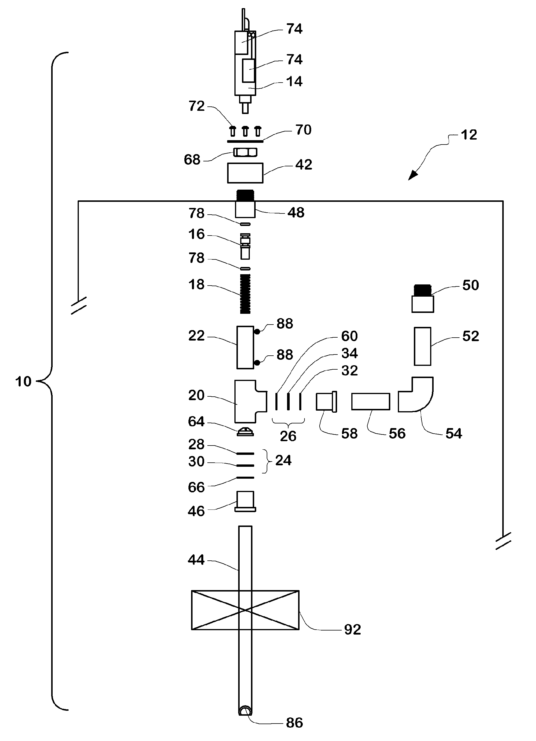
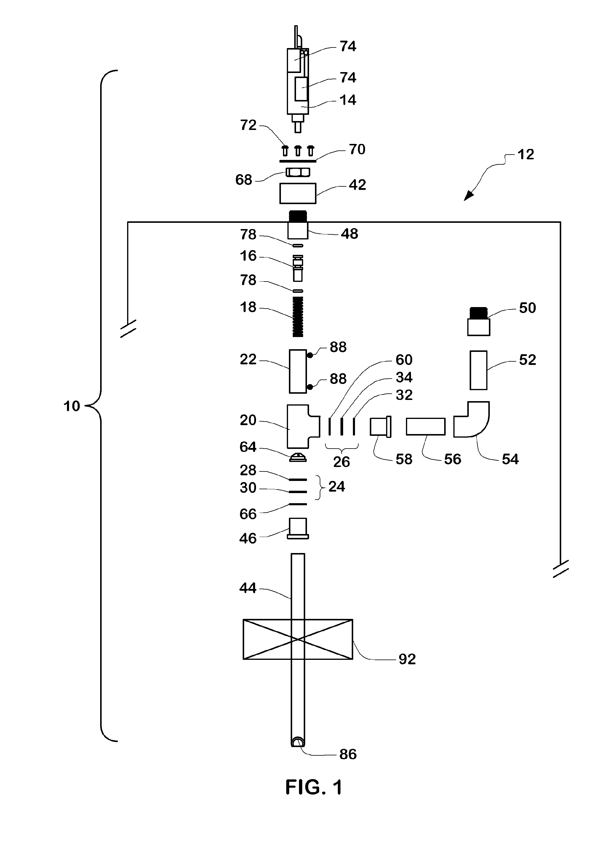
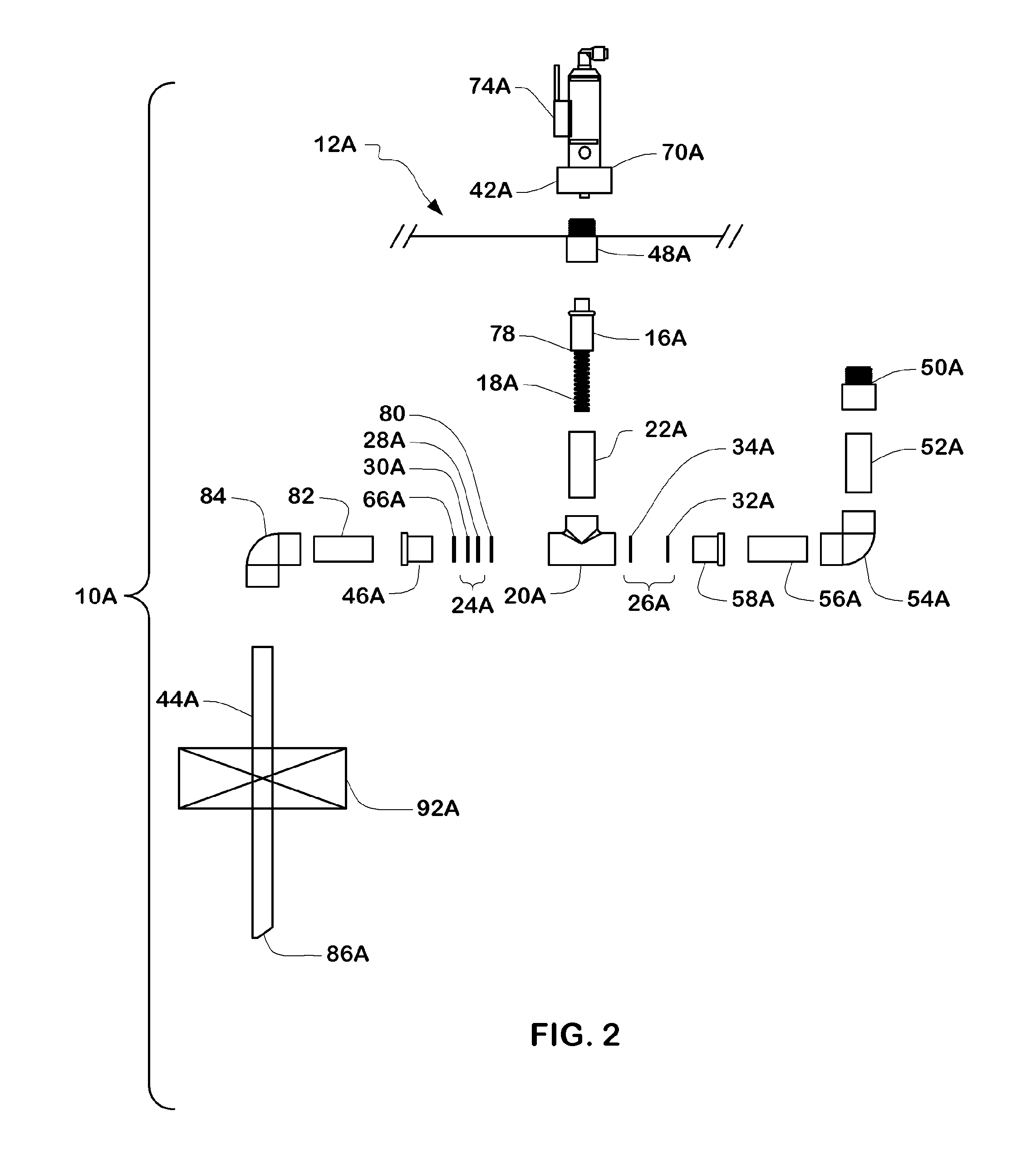
[0026]In this invention the preferred embodiment of the pump is constructed from an assortment of PVC pipe fittings, generally and preferably two PVC elbows, two reducing bushings, a PVC “T”, two straight PVC adaptors, and some PVC pipe. Most of these parts are available for less then thirty cents each.

[0027]In addition, in the preferred embodiment of the pump there is preferably a piston, two check valves, three washers, a spring, and three O-rings.

[0028]When the pump “body”, namely the assembled PVC parts, and especially the PVC “T”, is preferably inside the drum, two adaptors protrude through holes in the lid. One is for external connection of the air cylinder to drive the piston of the pump. The other is the pumped liquid color outlet connection.

[0029]An air cylinder, to actuate the piston, is preferably connected to a fitting, and then is preferably disconnected when the drum is empty, for connection to the next drum. The air cylinder part of the pump system is preferably not d...


PUM


Abstract

A pump has a PVC “T” shaped member having an inlet, an outlet and an interior pumping chamber positioned between the inlet and outlet; a piston displaceable into the chamber; an air cylinder for driving the piston into the chamber; a spring for biasing the piston outwardly from the chamber in opposition to force applied by the air cylinder; a washer-urethane disk check valve at the conduit inlet permitting fluid flow into the chamber but precluding fluid flow out of the chamber responsively to piston displacement into the chamber; and a washer-urethane disk check valve at the conduit outlet permitting fluid flow out of the chamber responsively to fluid pressure increase resulting from piston displacement into the chamber.

Description

BACKGROUND OF THE INVENTION[0001]1. Field of the Invention[0002]This invention relates to storage, handling and dispensing of liquid color for use in plastic fabricating, specifically in injection and compression molding, and in extrusion.[0003]2. Description of the Prior Art and Commercial Practice[0004]The “pump in a drum” concept is that every drum filled with liquid color has a pump included within it. This relieves the liquid color customer from having to own and from maintaining the pump, and from moving the pump from drum to drum. Liquid color can be very messy and difficult to handle, like oil-based paint, so it is desirable to eliminate or minimize the handling of liquid color-contaminated parts, pumps, tubing, etc.[0005]Because pumps are costly, the empty liquid color drum, with the pump inside, must be returned for refill. The cost of pumps currently used is around $100.00, which is too high to throw away the pump with the drum.[0006]Returning the drum presents its own se...

Claims


Application Information

Patent Timeline
Patent Type & Authority Patents(United States)
IPC IPC(8): B65D88/54B05B11/00F04B9/12F04B9/127F04B13/00F04B15/00F04B53/10
CPCF04B13/00F04B15/00F04B9/1215F04B53/1062F04B9/127
Inventor MAGUIRE, PAUL SHERWOODMAGUIRE, STEVEN B.
Owner MAGUIRE PROD
Why Eureka
Try Eureka