Specific gravity measuring apparatus

a technology of specific gravity and measuring apparatus, which is applied in the direction measuring devices, instruments, etc., can solve the problems of reducing affecting and giving a physical shock to the interior of the weighing apparatus, so as to improve the accuracy of specific gravity measurement and facilitate the operation of tasks. , the effect of laborious opening and closing operations

Active Publication Date: 2014-08-19
ALFA MIRAGE
View PDF12 Cites 0 Cited by
  • Summary
  • Abstract
  • Description
  • Claims
  • Application Information

AI Technical Summary

Benefits of technology

[0005]In view of the afore-described circumstances, the present invention aims at providing a specific gravity measuring apparatus which does not need to open and close the aerial mounting member each time and can improve specific gravity measurement accuracy. Described with reference symbols of an embodiment described later just for reference, a specific gravity measuring apparatus as set forth in claim 1 includes a liquid bath 1 filled with a liquid L, a measured object receiving member 3 which is housed in the liquid bath 1 via a support means 2 in a non-contact manner and into and out of which the liquid L within the liquid bath 1 can freely flow, an aerial mounting member 4 which is supported by the support means 2 and on which a measured object M is placed in order to measure gravity thereof in the air, and a weighing apparatus 5 receiving and supporting the measured object receiving member 3 via the support means 2, the weighing apparatus 5 being provided with a sensor 6 converting a weight acted upon the measured object receiving member 3 into an electrical signal and a measuring section 7 measuring specific gravity of the measured object M from an output of the sensor 6 at the time when the measured object M is placed on the aerial mounting member 4 and an output of the sensor 6 at the time when the measured object M is submerged and placed on the measured object receiving member 3, wherein the aerial mounting member 4 is provided in such a manner as to cover a part of an opening O at an upper part of the liquid bath 1 and leave the remainder open but not to fully cover the opening O, and the measured object M having been placed on the mounting member 4 can be dropped onto the measured object receiving member 3 directly.
[0006]According to the thus configured specific gravity measuring apparatus of the present invention, the aerial mounting member 4 is provided in such a manner as to cover a part of the opening O at the upper part of the liquid bath 1 and leave the remainder open but not to fully cover the opening O as in the conventional specific gravity measuring apparatus, and the measured object M having been placed on the mounting member 4 can be dropped onto the measured object receiving member 3 directly. Thus, there is no need to open and close the aerial mounting member each time as in the conventional apparatus, and accordingly, labor of the opening and closing operation of the aerial mounting member can be saved and tasks can be performed easily. In addition, no physical shock is given to the interior of the weighing apparatus 5, so that the possibility of causing subtle variations in measured values is eliminated and specific gravity measurement accuracy can be improved.
[0007]To carry out the above-configured present invention, more specifically, as set forth in claim 2, the support means 2 is constituted by a support frame body 13 integrally formed into a substantially square frame shape by four columns 11 and transverse frames 12 connecting the columns 11 together, four cable bodies 14 for hanging and supporting the measured object receiving member 3, the cable bodies 14 being hung down from respective upper ends of the columns 11 of the square frame-shaped support frame body 13, and a bottom frame body 15 fixed to a receiving portion 6a of the sensor 6 of the weighing apparatus 5 and supporting lower ends of the columns 11 of the square frame-shaped support frame body 13. By thus configuring the support means 2, the structure thereof is simplified and a reduction in weight thereof can be achieved. As a result, the measurement accuracy can be improved, and assembly and disassembly of the support means 2 can be facilitated.
[0008]Further, as set forth in claim 3, the columns 11 of the square frame-shaped support frame body 13 of the support means 2 have upper ends provided with four support arms 16 in a diagonal direction of the support frame body 13. The support arms 16 have distal ends from which protruding portions 16a are protruded, and to the protruding portions 16a, upper ends of the cable bodies 14 are fixed. The cable bodies 14 have lower ends fixed to protruding portions 3d provided at necessary places of an outer periphery of the measured object receiving member 3, and the measured object receiving member 3 is hung and supported by those four cable bodies 14. Accordingly, installation operation of the measured object receiving member 3 by the cable bodies 14 is facilitated. Further, as set forth in claim 4, the measured object receiving member 3 is composed of a bottom plate 3a and a peripheral wall 3b projected along a peripheral edge of the bottom plate 3a, and the bottom plate 3a is provided with a plurality of through holes 3c. By such configuration, the measured object receiving member 3 can easily be formed by, for example, plastic molding.
[0009]As set forth in claim 5, the aerial mounting member 4 is configured to have a proximal end pivotally fitted to the support means 2 and change its posture between a horizontal posture of covering a part of the opening O and a rising posture of rising from the horizontal posture. With this configuration, storing operation of the liquid bath 1 is simplified and facilitated by bringing the aerial mounting member 4 into the rising posture when the liquid bath 1 is stored within the support means 2 prior to the use of the specific gravity measuring apparatus. As set forth in claim 6, a configuration is employed that the aerial mounting member 4 is composed of a flat plate 4a and a measured object mounting portion 4b integrally projected along the flat plate 4a from a center of a distal end of the flat plate 4a and formed into a gentle concave dished shape and that the measured object M is placed on this gentle concave dish-shaped measured object mounting portion 4b. With that, unfavorable situations such as an accidental rolling-down of the measured object M from the aerial mounting member 4 can be prevented as long as the measured object measured object M is placed on the concave dish-shaped measured object mounting portion 4b at the time of measurement. Further, since the concave dish-shaped measured object mounting portion 4b is of a gentle concave dished shape, there is no problem in dropping the measured object M into the liquid bath 1, and the measured object M can be dropped easily. Moreover, as set forth in claim 7, if a configuration is employed that the aerial mounting member 4 has a distal end to which an extension member 24 formed in such a size that covers the remainder of the opening O and extending the aerial mounting member 4 is detachably connected so as to be flush with the aerial mounting member 4, a measured object M too large to be mounted on the aerial mounting member 4 can be placed and a measurement thereof can be carried out.

Problems solved by technology

In addition to that the opening and closing operation is troublesome, the opening and closing action of the aerial mounting member gives a physical shock to the interior of the weighing apparatus.
This can disadvantageously cause subtle variations in measured values and reduce specific gravity measurement accuracy.

Method used


Image

  • Specific gravity measuring apparatus
  • Specific gravity measuring apparatus
  • Specific gravity measuring apparatus

Examples


Embodiment Construction

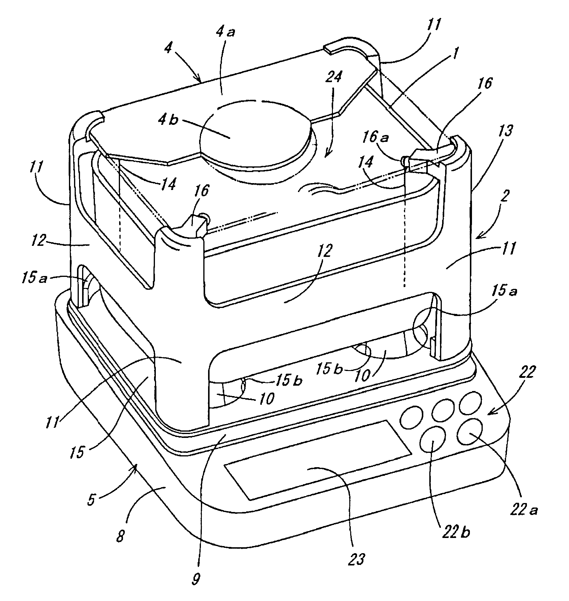
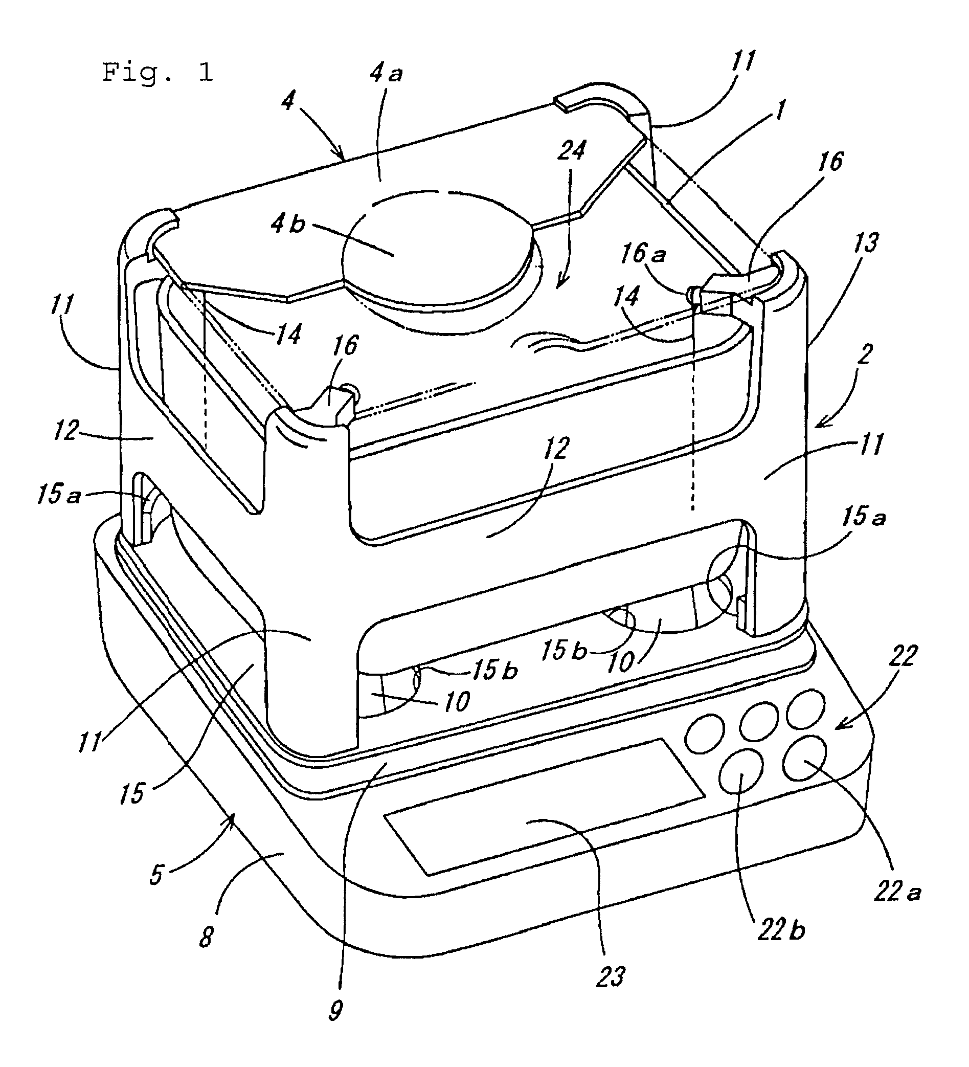
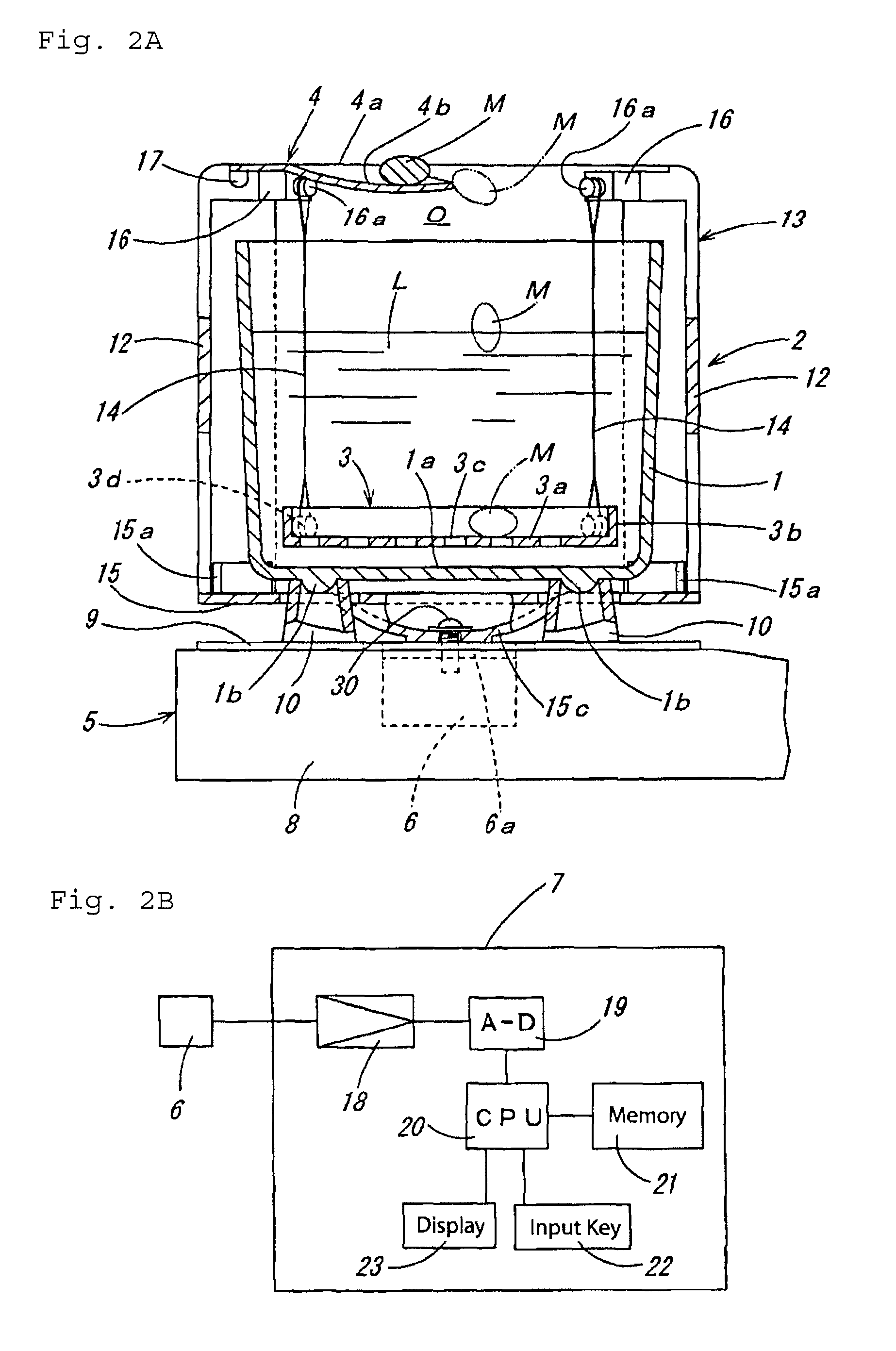
[0019]Hereinafter, a preferred embodiment of the present invention will be described based on the drawings. In FIG. 1 and FIG. 2A, a specific gravity measuring apparatus includes an angular cylindrical liquid bath 1 filled with a liquid L, a measured object receiving member 3 which is housed in the liquid bath 1 via a support means 2 in a non-contact manner and into and out of which the liquid L within the liquid bath 1 can freely flow, an aerial mounting member 4 which is supported by the support means 2 and on which a measured object M is placed in order to measure gravity thereof in the air, and a weighing apparatus 5 receiving and supporting the measured object receiving member 3 via the support means 2, the weighing apparatus 5 being provided with an electromagnetic-type sensor 6 converting a weight acted upon the measured object receiving member 3 into an electrical signal and a measuring section 7 measuring specific gravity of the measured object M from an output of the senso...


PUM

PropertyMeasurementUnit
specific gravityaaaaaaaaaa

Abstract

A specific gravity measuring apparatus includes a liquid bath, a measured object receiving member which is housed in the liquid bath via a support means in a non-contact manner and into and out of which a liquid within the liquid bath can freely flow, an aerial mounting member which is supported by the support means and on which a measured object is placed in order to measure gravity thereof in the air, and a weighing apparatus receiving and supporting the measured object receiving member via the support means. The weighing apparatus 5 is provided with a sensor and a measuring section. The aerial mounting member is provided in such a manner as to cover a part of an opening O at an upper part of the liquid bath.

Description

CROSS-REFERENCE TO RELATED APPLICATIONS[0001]The present application claims priority of Japanese patent application No. 2011-221503 filed on Oct. 6, 2011, the content of which is incorporated herein by reference.FIELD OF THE INVENTION[0002]The present invention relates to a specific gravity measuring apparatus for measuring specific gravity of solids and is used to find purity of, for example, gold and platinum or physical properties of solids such as rubber, plastic, etc.BACKGROUND OF THE INVENTION[0003]Conventional specific gravity measuring apparatuses include one which is described in Japanese examined utility model registration publication No. H04-49571. This specific gravity measuring apparatus is composed of a liquid bath filled with a liquid, a measured object receiving member which is housed in the liquid bath via a support means in a non-contact manner and into and out of which the liquid within the liquid bath can freely flow, an aerial mounting member which is supported ...

Claims


Application Information

Patent Timeline
Patent Type & Authority Patents(United States)
IPC IPC(8): G01N9/10G01N9/08G01N9/36
CPCG01N9/36G01N9/08
Inventor KONDO, SADANORI
Owner ALFA MIRAGE
Why Eureka
Try Eureka