
Linear fresnel solar arrays

a solar array and linear fresnel technology, applied in the direction of solar heat collector mounting/support, solar heat collector safety, light and heating equipment, etc., can solve the problems of limiting ground utilization to approximately 70% and reducing system performance, and achieve the effect of maximizing the annualized solar radiation collection efficiency of the solar energy collector system

Inactive Publication Date: 2014-08-19
AREVA SOLAR
View PDF379 Cites 9 Cited by
  • Summary
  • Abstract
  • Description
  • Claims
  • Application Information

AI Technical Summary

Benefits of technology

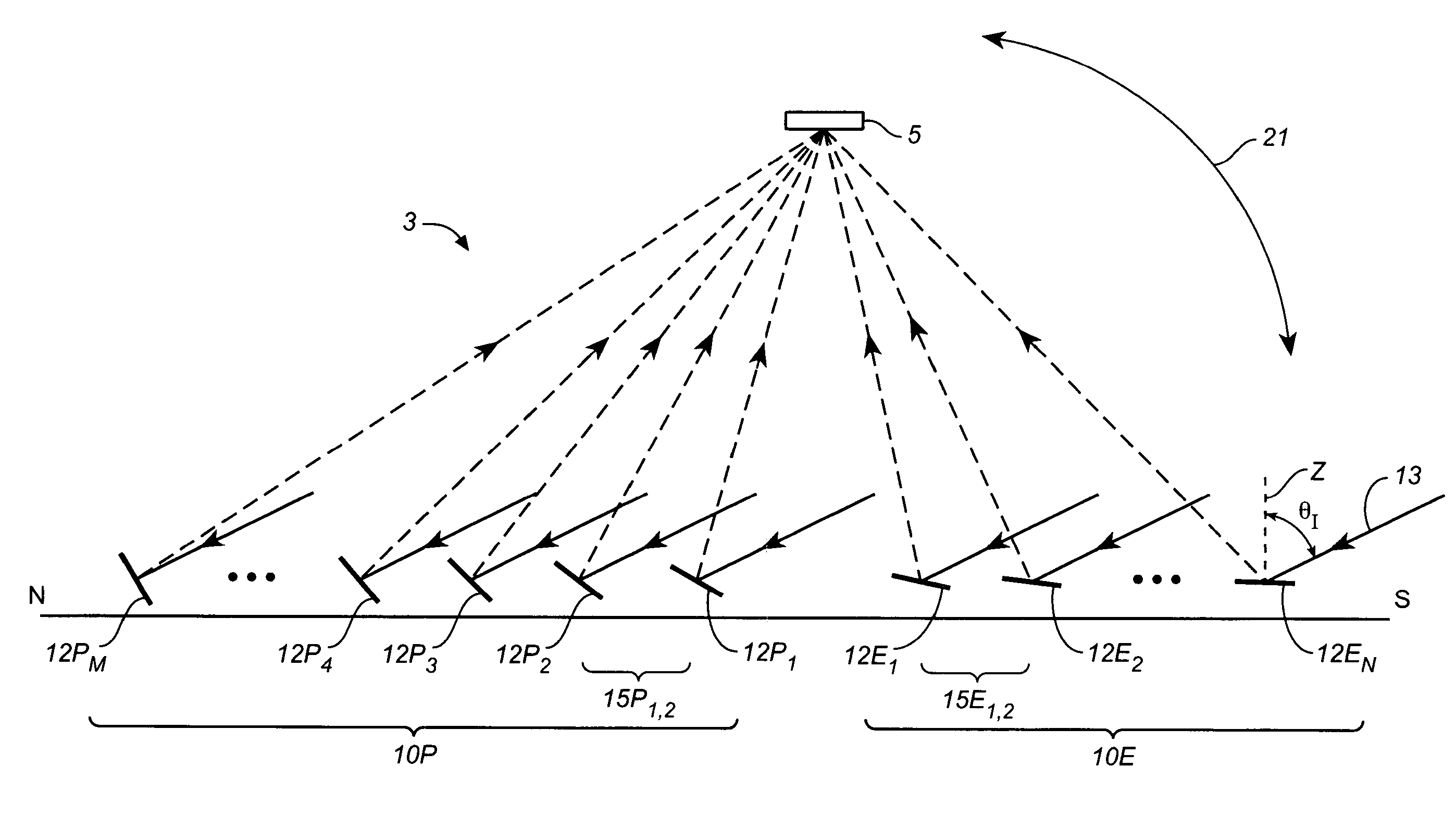
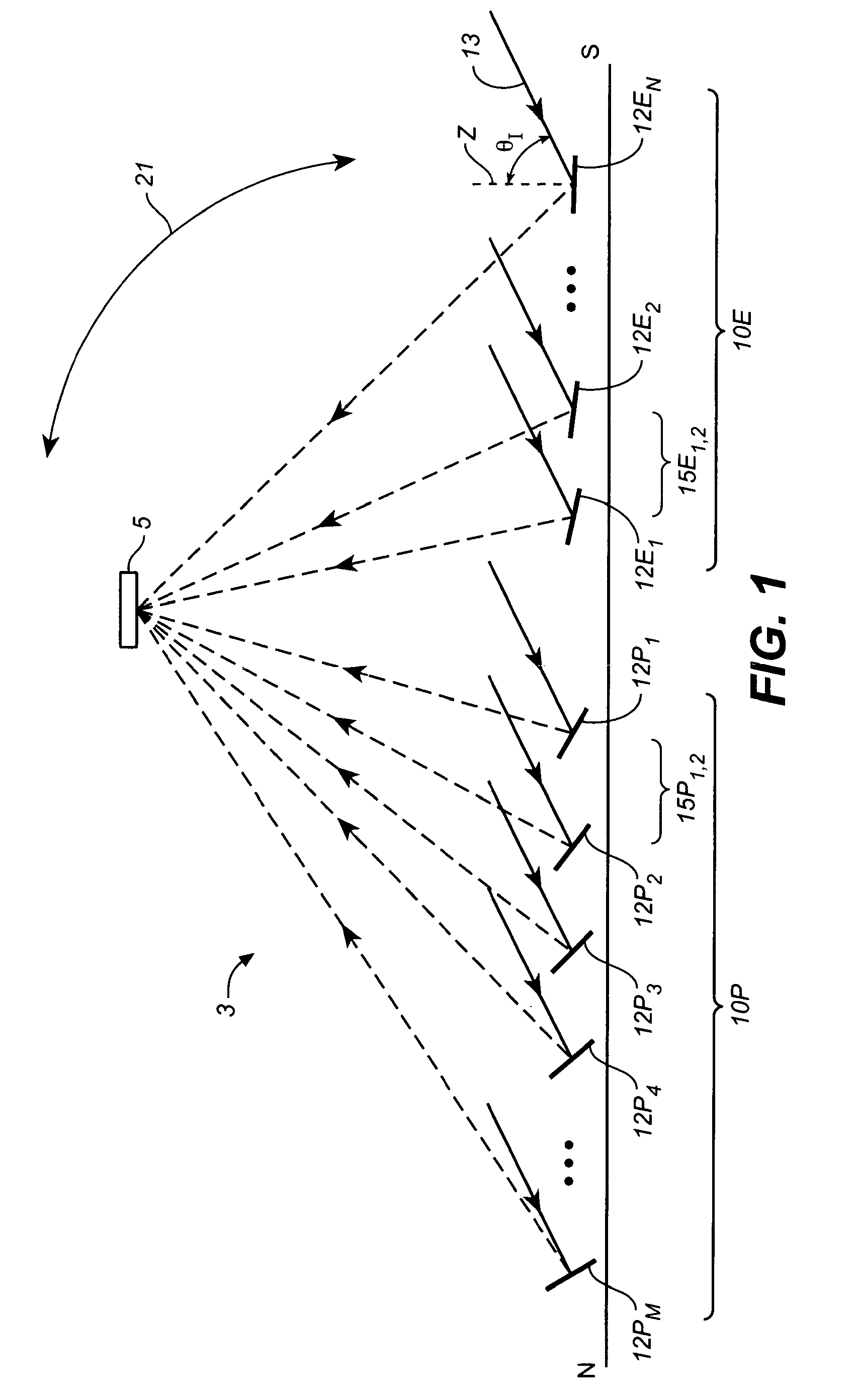
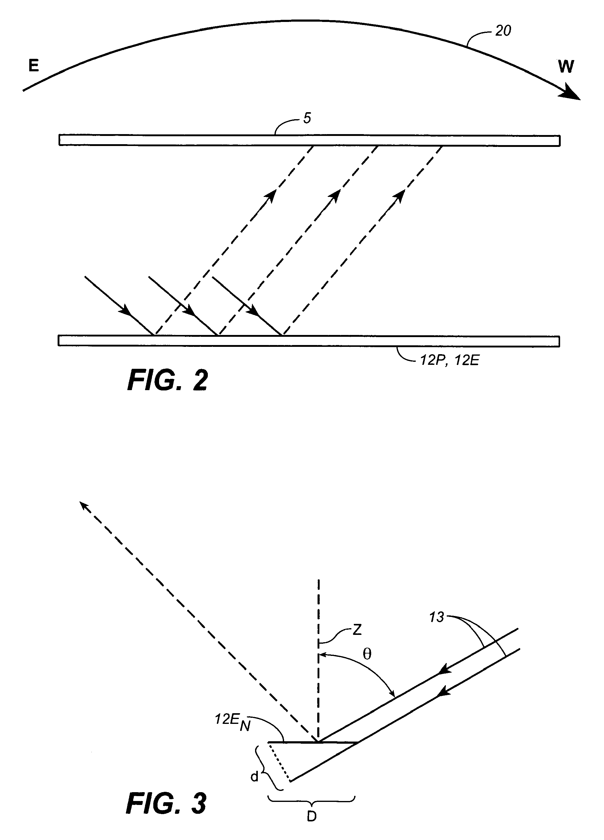
The invention is a system that collects solar energy using a linear receiver with a window and reflector fields on either side. The reflector fields are designed to maintain reflection of sunlight to the absorber through the window during the day. The window has a special coating that increases the amount of sunlight collected. The technical effect of the invention is to provide a more efficient way to collect solar energy.

Problems solved by technology

This limits ground utilization to approximately 70% and diminishes system performance due to exacerbated spillage at the receiver of radiation from distant reflectors.

Method used


Image

  • Linear fresnel solar arrays
  • Linear fresnel solar arrays
  • Linear fresnel solar arrays

Examples


Embodiment Construction

[0026]The following detailed description should be read with reference to the drawings, in which identical reference numbers refer to like elements throughout the different figures. The drawings, which are not necessarily to scale, depict selective embodiments and are not intended to limit the scope of the invention. The detailed description illustrates by way of example, not by way of limitation, the principles of the invention. This description will clearly enable one skilled in the art to make and use the invention, and describes several embodiments, adaptations, variations, alternatives and uses of the invention, including what is presently believed to be the best mode of carrying out the invention.

[0027]In addition, it must be noted that, as used in this specification and the appended claims, the singular forms “a,”“an,” and “the” include plural referents unless the context clearly indicates otherwise. Also, the term “parallel” is intended to mean “substantially parallel” and t...


PUM

PropertyMeasurementUnit
angleaaaaaaaaaa
angleaaaaaaaaaa
areaaaaaaaaaaa

Abstract

Disclosed herein are examples and variations of solar energy collector system comprising an elevated linear receiver (5) and first and second reflector fields (10P, 10E) located on opposite sides of, and arranged and driven to reflect solar radiation to, the receiver (5). Also disclosed herein are examples and variations of receivers (5) and reflectors (12a) that may, in some variations, be utilized in the disclosed solar energy collector systems.

Description

CROSS-REFERENCE TO RELATED APPLICATIONS[0001]This application is a National Phase filing under 35 U.S.C. §371 of International Application No. PCT / US2008 / 010230, filed on Aug. 27, 2008, which claims the benefit of priority to U.S. Provisional Application Ser. No. 61 / 007,926 filed Aug. 27, 2007, entitled “Linear Fresnel Solar Arrays,” which is incorporated by reference herein in its entirety. This application also claims the benefit of priority to U.S. patent application Ser. No. 12 / 012,920 filed Feb. 5, 2008, entitled “Linear Fresnel Solar Arrays and Components Therefor,” U.S. patent application Ser. No. 12 / 012,829 filed Feb. 5, 2008, entitled “Linear Fresnel Solar Arrays and Receivers Therefor,” and U.S. patent application Ser. No. 12 / 012,821 filed Feb. 5, 2008, entitled “Linear Fresnel Solar Arrays and Drives Therefor,” each of which is incorporated by reference herein in its entirety.BACKGROUND OF THE INVENTION[0002]Solar energy collector systems of the type referred to as Linear...

Claims


Application Information

Patent Timeline
Patent Type & Authority Patents(United States)
IPC IPC(8): F24J2/38F24S10/70F24S20/20F24S23/70F24S23/77F24S50/20
CPCF24J2/464F24J2/541H01L31/0522F24J2/07Y10T24/39Y02E10/52Y10T29/53Y02E10/45F24J2002/5458Y02E10/44H01L31/0547H01L31/054F24J2/245F24J2/523Y02E10/41F24J2/14F24J2002/108F24J2/16Y02E10/47F24S40/80F24S2025/017F24S2025/014F24S20/20F24S23/74F24S23/77F24S23/79F24S10/742F24S80/40F24S25/10F24S30/425F24S2023/872F24S2030/133F24S80/58Y02E10/40
Inventor MILLS, DAVID R.SCHRAMEK, PHILIPPLE LIEVRE, PETER K.DEGRAAFF, DAVID B.JOHNSON, PETER L.HOERMANN, ALEXANDER
Owner AREVA SOLAR
Learn More