LED-based lamps

a technology of led lamps and diodes, which is applied in the direction of fibre light guides, lighting and heating apparatus, semiconductor devices for light sources, etc., can solve the problems of reducing the uniformity of illumination within the emission angle, and the configuration is unsuitable for spotlights with lower angles, and achieves the effect of a large area

Inactive Publication Date: 2014-08-19
INTEMATIX
View PDF209 Cites 11 Cited by
  • Summary
  • Abstract
  • Description
  • Claims
  • Application Information

AI Technical Summary

Benefits of technology

[0009]Embodiments of the invention are directed to lamps in which light generated by one or more solid-state light sources, typically LEDs, is coupled into a first end of a light guide and is guided, by total internal reflection, through the light guiding medium to a light emitting surface that is located at or in proximity to a second end of the light guide that is remote to the LED. One or more phosphor materials, photoluminescent materials, are provided as a layer covering at least a part of the light emitting surface of the light guide which absorb a proportion of the LED light and in response emit light of a different color (typically of a longer wavelength). The emission product of the lamp comprises the combination of light emitted by the phosphor material and light generated by the LED that is not absorbed by the phosphor. Lamps in accordance with the invention provide a number of benefits including:
[0010]the ability to provide increased cooling of the LED(s) since they can be located remote to the point of light emission thereby enabling the LED(s) to be mounted to a larger thermal mass such as the connector base used to provide electrical power to the lamp,
[0011]reduced thermal degradation of the phosphor since it is located remote to the LED,

Problems solved by technology

However, as light emission from a lamp is confined within a selected emission angle this can result in a greater proportion of the light emission being concentrated on the axis thereby further reducing illuminance uniformity within the emission angle.
Whilst such a configuration can produce a good uniform illumination for emission angles of 40° and greater such a configuration is unsuitable for spotlights with lower emission angles and in particular spotlights with a compact form factor such as for example MR16 lamps.

Method used


Image

  • LED-based lamps
  • LED-based lamps
  • LED-based lamps

Examples


Embodiment Construction

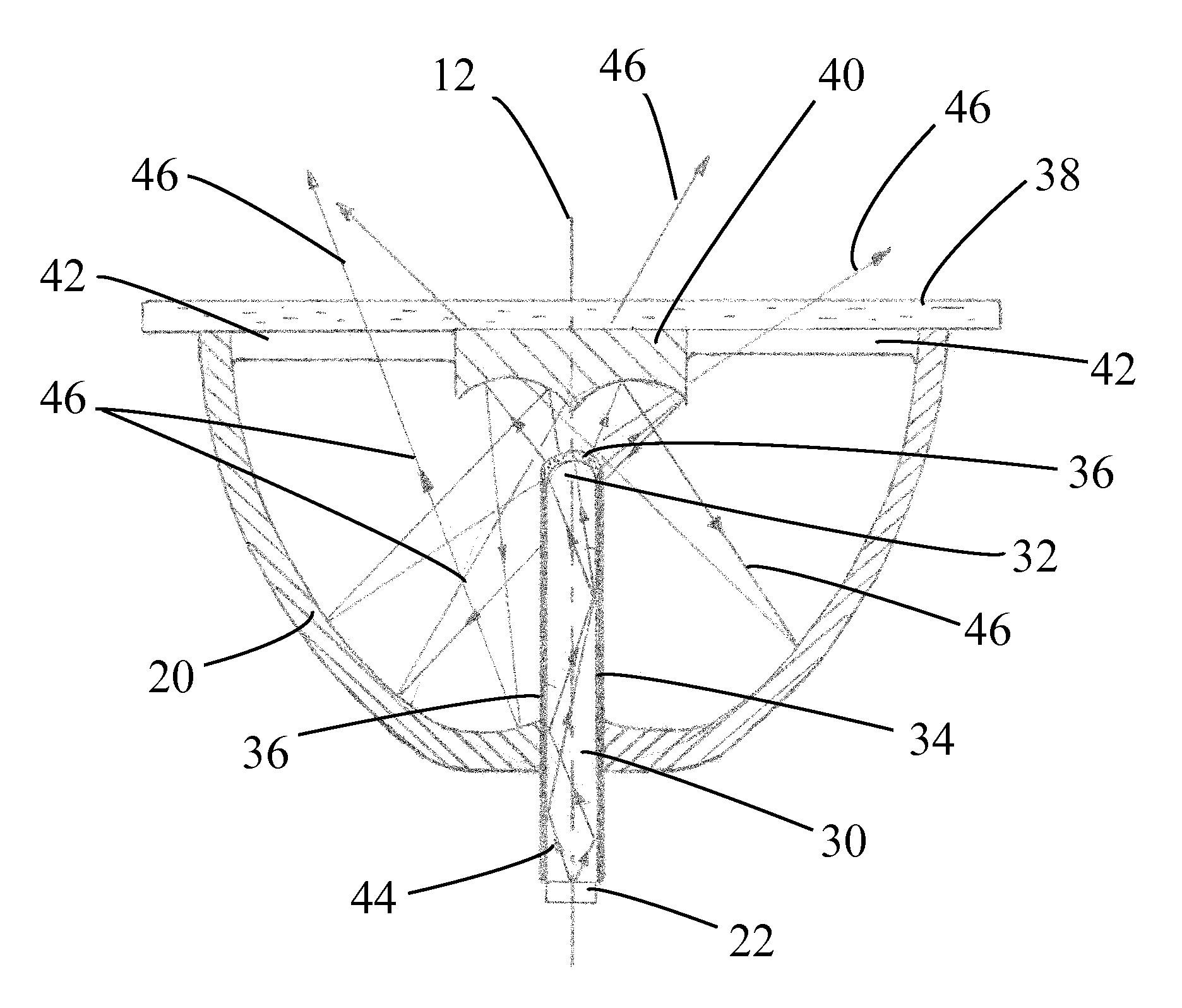
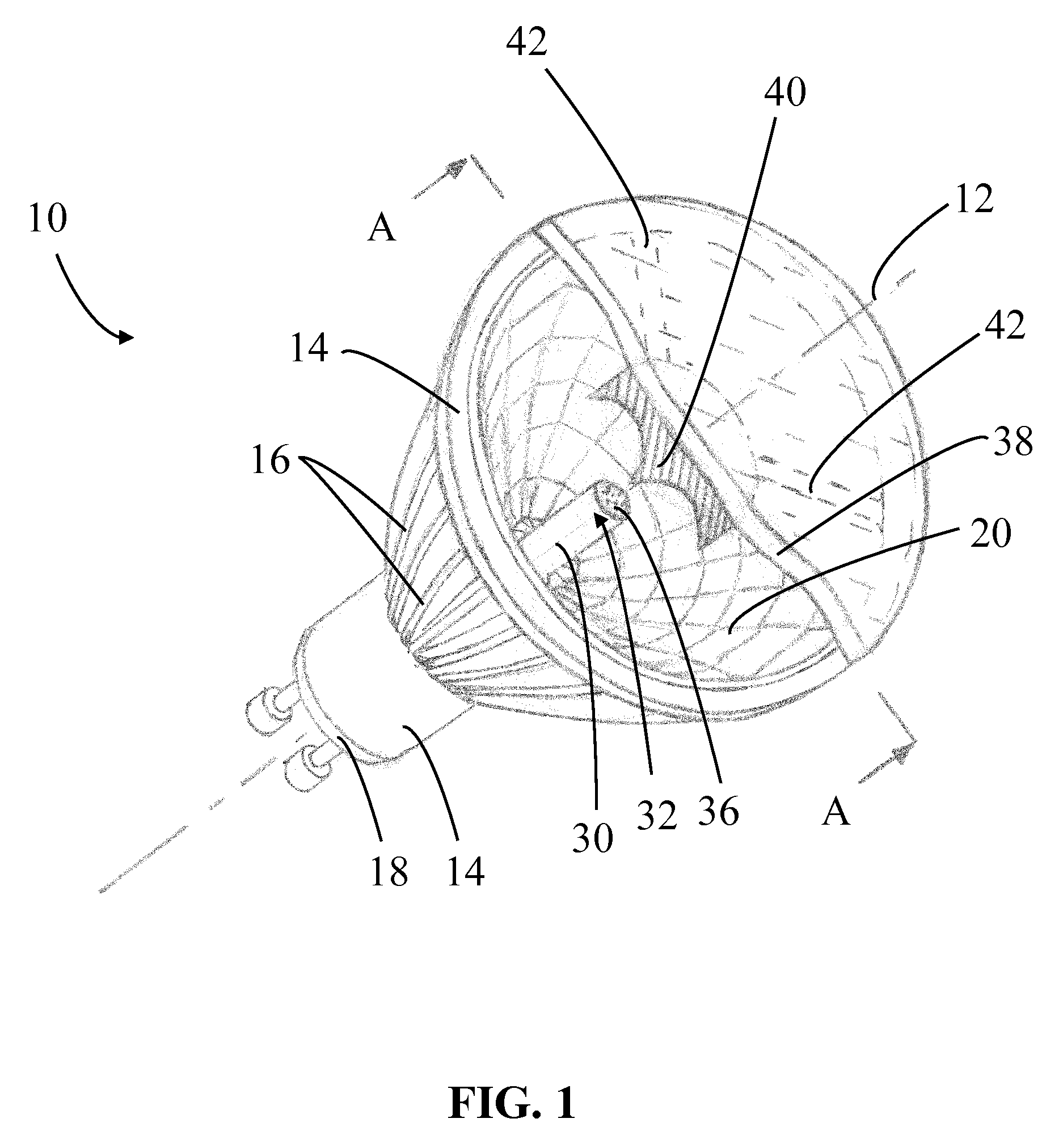
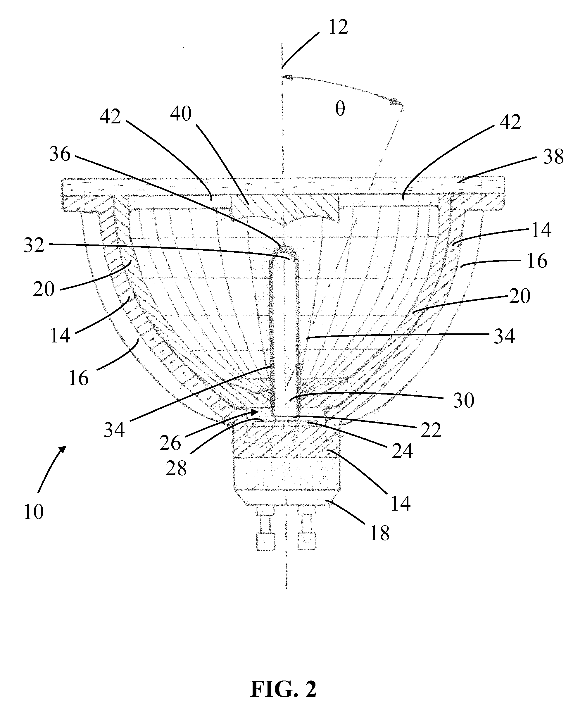
[0034]Embodiments of the invention are directed to LED-based lamps in which light generated by one or more LEDs is coupled into a first end of a light guide and is waveguided, by total internal reflection, through the light guiding medium to a light emitting surface that is located remote to the LED(s). One or more phosphor materials, photoluminescent materials, is / are provided on, or in proximity to, the light emitting surface of the waveguide and absorbs a proportion of the LED light and in response emits light of a different color (typically of a longer wavelength) which combined with the LED light that is not absorbed by the phosphor comprises light emitted by the lamp.

[0035]In one arrangement the lamp can be configured as a spotlight and comprises a dish-shaped reflector, typically generally parabolic in form, and an elongate light guide that extends along the axis of the reflector and is configured to emit light in a direction toward the reflector. The one or more LEDs can be ...


PUM

PropertyMeasurementUnit
emission angleaaaaaaaaaa
emission anglesaaaaaaaaaa
Correlated Color Temperatureaaaaaaaaaa

Abstract

A lamp comprises: a dish-shaped (parabolic); an LED operable to generate excitation light; a light guide configured to extend along an axis of the reflector, wherein light generated by the at least one LED is coupled into a first end of the light guide and wherein light is emitted from the light guide at a light emitting surface that is in proximity to a second end of the light guide and at least one phosphor material provided as a layer on at least a part of the light emitting surface of the light guide. An LED light bulb is also disclosed.

Description

CLAIM OF PRIORITY[0001]This application claims the benefit of priority to U.S. Provisional Patent application 61 / 354,068, filed Jun. 11, 2010, entitled “LED Lamp”, by Li et al., the specification and drawings of which are incorporated herein by reference.BACKGROUND OF THE INVENTION[0002]1. Field of the Invention[0003]This invention relates to LED (Light Emitting Diode) based lamps and in particular, although not exclusively, to LED based spotlights.[0004]2. Description of the Related Art[0005]White light emitting LEDs (“white LEDs”) are known in the art and are a relatively recent innovation. It was not until LEDs emitting in the blue / ultraviolet part of the electromagnetic spectrum were developed that it became practical to develop white light sources based on LEDs. As taught, for example in U.S. Pat. No. 5,998,925, white LEDs include one or more phosphor materials, that is photo-luminescent materials, which absorb a portion of the radiation emitted by the LED and re-emit radiation...

Claims


Application Information

Patent Timeline
Patent Type & Authority Patents(United States)
IPC IPC(8): F21V7/00F21V29/00F21Y101/02F21V7/22F21V7/06F21W121/00F21K99/00F21V3/04F21V7/20F21V29/505
CPCF21V7/0008F21K9/56F21V29/2231F21K9/135F21K9/52G02B6/0008F21V7/0025F21K9/137G02B6/0003F21Y2101/02F21V7/20F21V3/0481F21V7/06F21V3/0463F21W2121/00F21V7/22F21V29/773F21V29/505F21K9/232F21K9/233F21K9/61F21K9/64F21Y2115/10F21V3/08F21V3/12F21V7/24F21V7/28F21V7/00G02B6/0001
Inventor LI, YI-QUNCOLLIER, IAN
Owner INTEMATIX
Why Eureka
Try Eureka