Battery control device and battery control method

a battery control device and control method technology, applied in the direction of secondary cell servicing/maintenance, electrochemical generators, transportation and packaging, etc., can solve the problems of unnecessary correction of the calculated value of the discharge capacity and unwoidly undesirable improper correction

Active Publication Date: 2014-08-19
NGK INSULATORS LTD
View PDF10 Cites 9 Cited by
  • Summary
  • Abstract
  • Description
  • Claims
  • Application Information

AI Technical Summary

Benefits of technology

[0029]According to the present invention, since the secondary battery where the estimated error exceeds the first threshold is the candidate for the correction of the calculated value of the discharge capacity, the calculated value of the discharge capacity in the secondary battery requiring the correction of the calculated value of the discharge capacity is corrected, and the calculated value of the discharge capacity that does not require the correction is not corrected.
[0030]According to the second invention, the secondary battery where an error is accumulated in the calculated value of the discharge capacity quickly becomes the target for the correction of the calculated value of the discharge capacity, and thus the calculated value of the discharge capacity is corrected on a timely basis.
[0031]According to the third invention, since the secondary battery where an error of the calculated value of the discharge capacity becomes easily large quickly becomes the target for the correction of the calculated value of the discharge capacity, the calculated value of the discharge capacity is corrected on a timely basis.
[0032]According to the fourth invention, the secondary battery where an error caused by a response speed of the current measuring part, a frequency characteristic of the current measuring part, a measurement interval of the charge / discharge current value and so on greatly influence the calculated value of the discharge capacity quickly becomes the target for the correction of the calculated value of the discharge capacity. For this reason, the calculated value of the discharge capacity is corrected on a timely basis.
[0033]According to the fifth invention, the secondary battery, where an error caused by a non-linear property of the current measuring part, an error that is included in the measured value of the current measuring part and is proportional to the measured value of the current measuring part and so on greatly influence the calculated value of the discharge capacity, quickly becomes the target for the correction of the calculated value of the discharge capacity. For this reason, the calculated value of the discharge capacity is corrected on a timely basis.
[0034]According to the sixth invention, the secondary battery, where an error caused by stopping the integration of the charge / discharge current value in the discharge capacity calculator greatly influences the calculated value of the discharge capacity, quickly becomes the target for the correction of the calculated value of the discharge capacity. For this reason, the calculated value of the discharge capacity is corrected on a timely basis.

Problems solved by technology

However, the correction of the calculated value of the discharge capacity in Patent Document 1 occasionally causes problems that the correction of the calculated value of the discharge capacity in a NaS battery that requires the correction of the calculated value of the discharge capacity is delayed, and that the correction of the calculated value of the discharge capacity is corrected at time intervals that are shorter than necessary and thus unnecessary correction of the calculated value of the discharge capacity is made.
Such improper correction is not desirable because an output from a power storage device is greatly influenced.

Method used


Image

  • Battery control device and battery control method
  • Battery control device and battery control method
  • Battery control device and battery control method

Examples


first embodiment

[0062](1. First Embodiment)

[0063]A first embodiment relates to a power storage device 1002.

[0064](Outline of Power Storage Device 1002)

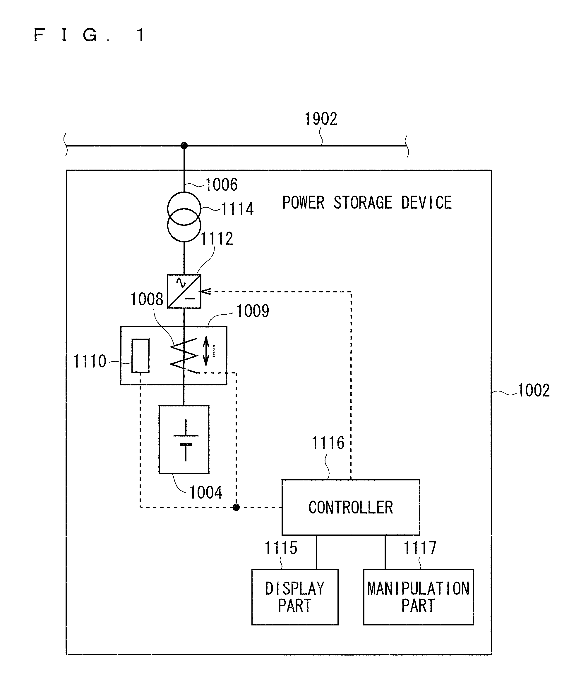
[0065]FIG. 1 is a block diagram illustrating the power storage device 1002 according to the first embodiment.

[0066]As shown in FIG. 1, the power storage device 1002 has a NaS battery (sodium-sulfur battery) 1004 for storing electric power, a connecting line 1006 for connecting a system 1902 and the NaS battery 1004, a Hall current detector 1008 for measuring a charge / discharge current value I of the NaS battery 1004, a housing 1009 for housing the Hall current detector 1008, a temperature sensor 1110 for measuring a temperature T inside the housing 1009, a bidirectional converter 1112 for converting electric power supplied from the NaS battery 1004 to the system 1902 from a direct current into an alternating current and converting electric power supplied from the system 1902 to the NaS battery 1004 from an alternating current into a direct current, a...

second embodiment

[0145](2. Second Embodiment)

[0146]A second embodiment relates to a power storage device 2002.

[0147](Outline of Power Storage Device 2002)

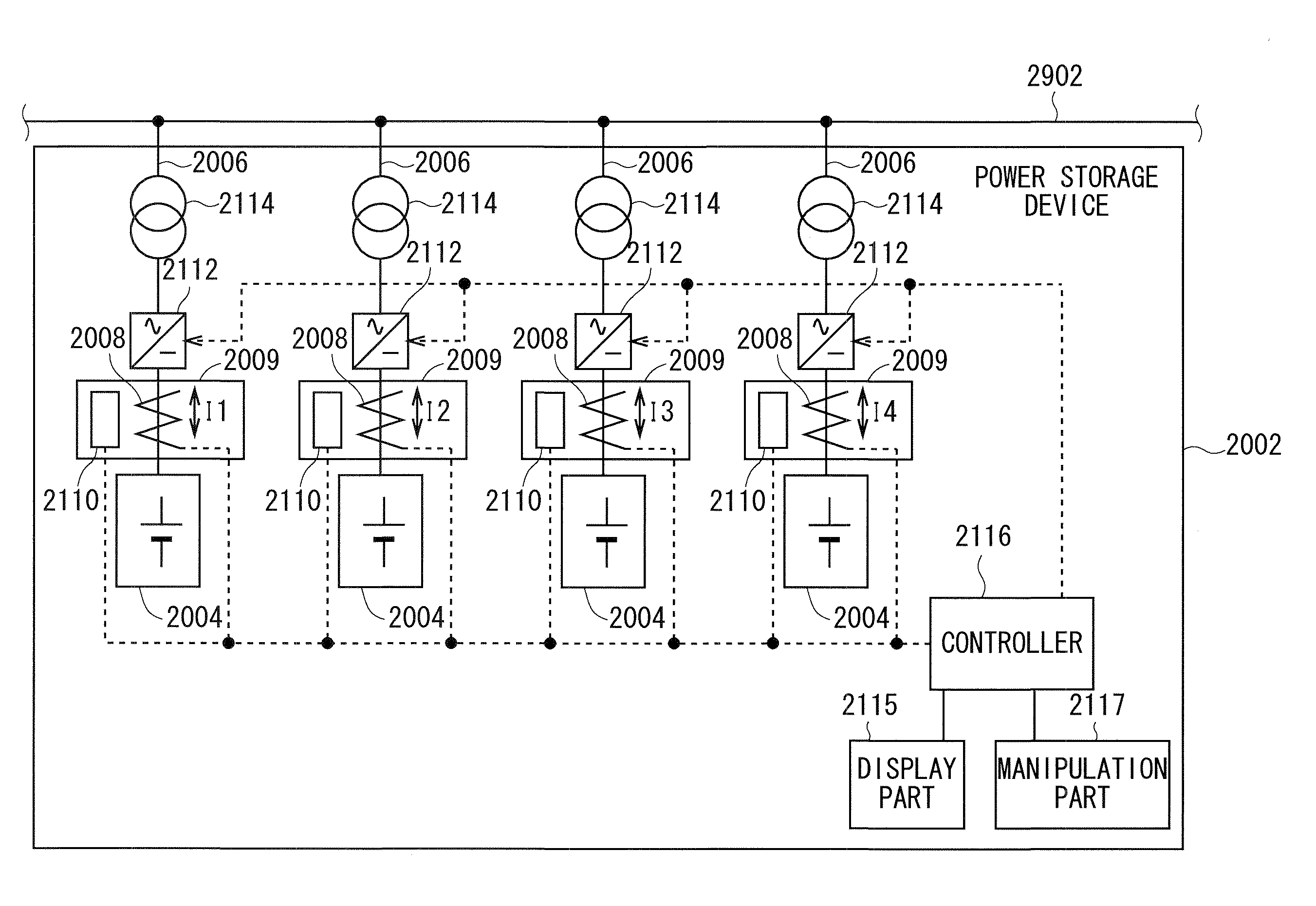
[0148]FIG. 6 is a block diagram illustrating the power storage device 2002 according to the second embodiment.

[0149]As shown in FIG. 6, the power storage device 2002 has NaS batteries 2004 for storing electric power, connecting lines 2006 for connecting a system 2902 and the NaS batteries 2004, Hall current detectors 2008 for measuring the charge / discharge current values Tm (m=1, 2, 3 and 4) of the NaS batteries 2004, housings 2009 for housing the Hall current detectors 2008, temperature sensors 2110 for measuring temperatures Tm (m=1, 2, 3 and 4) inside the housings 2009, bidirectional converters 2112 for converting electric power supplied from the NaS batteries 2004 to the system 2902 from a direct current into an alternating current and converting electric power supplied from the system 2902 to the NaS batteries 2004 from an alternating current ...

third embodiment

[0197](3. Third Embodiment)

[0198]A third embodiment relates to a correction target determinator 3134 that is adopted instead of the correction target determinator 2134 according to the second embodiment.

[0199]FIG. 10 is a block diagram illustrating the correction target determinator 3134 according to the third embodiment.

[0200]As shown in FIG. 10, the correction target determinator 3134 has a first comparator 3140 for comparing the estimated errors Erm(t2) with a first threshold TH1, a first threshold holding part 3142 for holding the first threshold TH1, a first selector 3144 for selecting the NaS batteries 2004 as the candidates for the correction of the calculated values of the discharge capacities, a second comparator 3150 for comparing the estimated errors Erm(t2) with a second threshold TH2, a second threshold holding part 3152 for holding the second threshold TH2, a second selector 3154 for selecting the NaS batteries 2004 as the targets for the correction of the calculated v...


PUM


Abstract

A power storage device has a NaS battery for storing electric power, a Hall current detector for measuring charge / discharge current value I of the NaS battery, a bidirectional converter for converting electric power between a direct current and an alternating current bidirectionally, and a controller for controlling the power storage device. The controller integrates the charge / discharge current value I of the NaS battery and calculates the calculated value of the discharge capacity in the NaS battery. The controller calculates estimated error Er(t2) of the calculated value of the discharge capacity, specifies NaS battery 1004 that requires the correction of the calculated value of the discharge capacity, charges / discharges the NaS battery to a depth of discharge at which the calculated value of the discharge capacity is corrected, and corrects the calculated value of the discharge capacity in the charged / discharged NaS battery.

Description

BACKGROUND OF THE INVENTION[0001]1 . Field of the Invention[0002]The present invention relates to a battery control device and a battery control method for controlling a secondary battery.[0003]2 . Description of the Related Art[0004]Patent Document 1 relates to control of charge / discharge of a plurality of NaS batteries.[0005]Patent Document 1 describes that when a power storage device having a plurality of NaS batteries provided to an electrical supply network is caused to follow a power source such as natural energy whose output changes irregularly for a short time, an error of a calculated value of a discharge capacity is easily generated, and thus the calculated value of the discharge capacity should be corrected.[0006]Further, Patent Document 1 describes that the calculated values of the discharge capacities in the NaS batteries are corrected sequentially one by one.PRIOR ART DOCUMENTPatent Document[0007]Patent Document 1: Japanese Patent Application Laid-Open No. 2008-84677SU...

Claims


Application Information

Patent Timeline
Patent Type & Authority Patents(United States)
IPC IPC(8): H02J7/00
CPCH01M10/3909H01M10/425H01M10/44H01M10/48H02J7/0011H02J7/0018H02J7/0022Y02E60/10H02J7/00
Inventor ABEHATTA, TETSUYA
Owner NGK INSULATORS LTD
Why Eureka
Try Eureka