Voltage regulator with transient response
a voltage regulator and transient response technology, applied in the direction of electric variable regulation, process and machine control, instruments, etc., can solve the problems of increasing the undershoot or overshoot of the output voltage vout in the load transient response, and achieve the effect of improving the transient response characteristics
- Summary
- Abstract
- Description
- Claims
- Application Information
AI Technical Summary
Benefits of technology
Problems solved by technology
Method used
Image
Examples
first embodiment
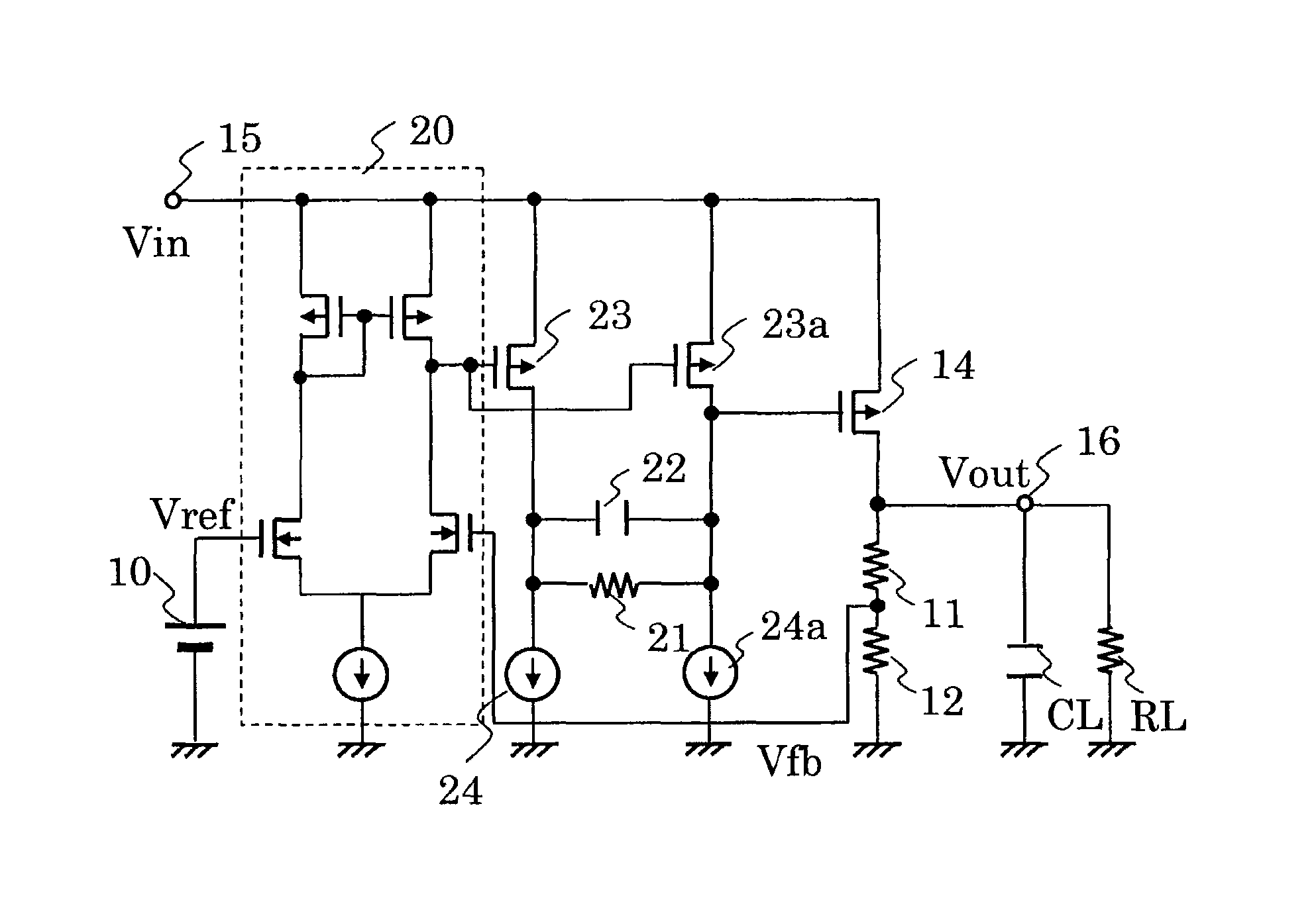
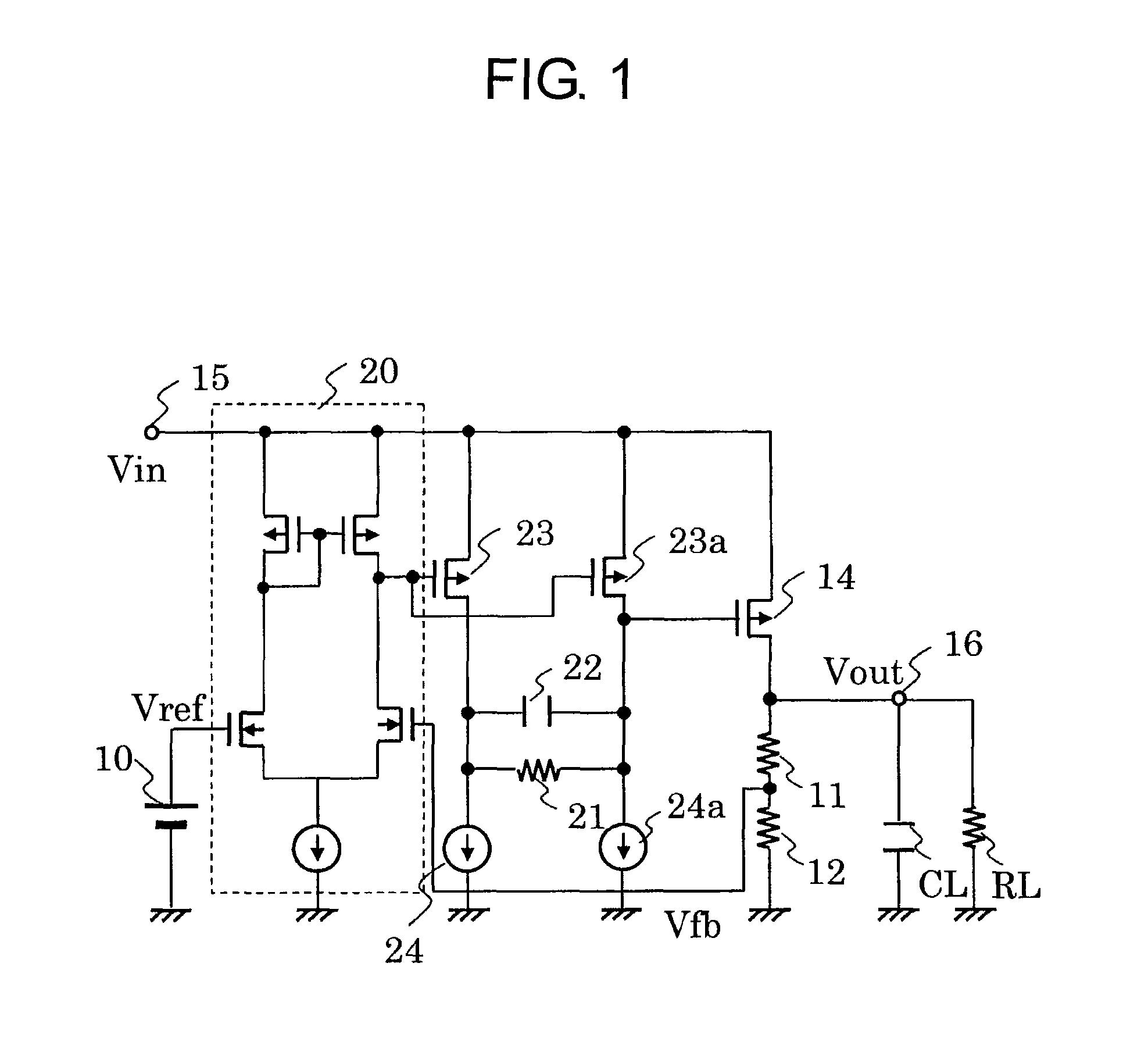
[0025]Referring to FIG. 1, there is provided a circuit diagram of a voltage regulator according to a first embodiment.
[0026]The voltage regulator according to the first embodiment includes a reference voltage circuit 10, a differential amplifier 20, MOS transistors 23 and 23a, constant current sources 24 and 24a, a resistor 21, a capacitor 22, a MOS transistor 14, which is an output MOS transistor, and bleeder resistors 11 and 12.
[0027]The bleeder resistors 11 and 12 generate a feedback voltage Vfb by dividing an output voltage Vout of an output terminal 16. The differential amplifier 20 compares a reference voltage output from the reference voltage circuit 10 with the feedback voltage Vfb. An output of the differential amplifier 20 is input to a gate terminal of the MOS transistor 23 constituting a first source ground amplifier circuit and to a gate terminal of the MOS transistor 23a constituting a third source ground amplifier circuit. The MOS transistor 23 has a source terminal, ...
second embodiment
[0041]FIG. 3 is a circuit diagram of a voltage regulator according to a second embodiment. The voltage regulator according to the second embodiment has an output load current detection circuit 30 which senses an output load current. Moreover, the constant current source 24a additionally has a switch circuit and a constant current source which are sequentially connected. The circuit configuration is the same as in the first embodiment except the output load current detection circuit 30 and the constant current source 24a.
[0042]The output load current detection circuit 30 has a terminal for outputting a detection signal connected to a switch circuit of the constant current source 24a. Further, the output load current detection circuit 30 switches the current value of the constant current source 24a according to the detection signal.
[0043]For example, in the case of an increase in an output load current, the output load current detection circuit 30 increases the current value of the c...
third embodiment
[0045]FIG. 4 is a circuit diagram of a voltage regulator according to a third embodiment.
[0046]The voltage regulator according to the third embodiment has an output load current detection circuit 30 which senses output load current. Moreover, the resistor 21 additionally has a switch circuit and a constant current source which are connected in parallel. The circuit configuration is the same as in the first embodiment except the output load current detection circuit 30 and the resistor 21.
[0047]The output load current detection circuit 30 has a terminal for outputting a detection signal connected to the switch circuit of the resistor 21. In addition, the output load current detection circuit 30 switches the resistance value of the resistor 21 according to the detection signal.
[0048]For example, in the case of an increase in an output load current, the output load current detection circuit 30 decreases the resistance value of the resistor 21. This enables the resistance value to be sw...
PUM
 Abstract
Description
Claims
Application Information
 - R&D
- Intellectual Property
- Life Sciences
- Materials
- Tech Scout
- Unparalleled Data Quality
- Higher Quality Content
- 60% Fewer Hallucinations
Browse by: Latest US Patents, China's latest patents, Technical Efficacy Thesaurus, Application Domain, Technology Topic, Popular Technical Reports.
© 2025 PatSnap. All rights reserved.Legal|Privacy policy|Modern Slavery Act Transparency Statement|Sitemap|About US| Contact US: help@patsnap.com


