Method and a device for transmission with time-frequency mapping of symbols in sub-channels

a time-frequency mapping and symbol technology, applied in the field of telecommunications, can solve the problems of limiting the performance of the decision circuit on reception, time correlation giving rise to error bursts, and the drawback of known symbol mapping techniques reducing or even eliminating the diversity effect associated, and achieve the effect of increasing the diversity

Active Publication Date: 2014-08-19
ORANGE SA (FR)
View PDF8 Cites 1 Cited by
  • Summary
  • Abstract
  • Description
  • Claims
  • Application Information

AI Technical Summary

Benefits of technology

[0052]During the mapping step, the symbols from the interleaving step are segmented into different sub-channels, which are themselves scattered in time and in frequency. Typically, a sub-channel contains symbols from a given user. Thus, with a plurality of users, the symbols from different users are segmented into different sub-channels. With different services for a given user, the respective symbols of the different services are typically segmented into different sub-channels. By way of example, such segmentation makes it possible to distinguish the quality of service (QoS) between services, by giving more sub-channels to one given service than to another (or by reserving a certain frequency bandwidth to a given service).
[0054]The method and the device in accordance with the invention solve the problem posed. When dimensioning the size of the sub-channels, by taking account of the mapping of the interleaved symbols over sub-channels that are allocated in time, in frequency, or both in time and in frequency, i.e. respectively between a plurality of multi-carrier symbols for a given frequency band, within a given multi-carrier symbol, or between a plurality of multi-carrier symbols, it is possible to keep away from potential values that give rise to the symbol interleaving pattern being repeated between sub-channels that are adjacent or between sub-channels that are not adjacent, being spaced apart to a greater or lesser extent depending on the implementation. A method of the invention provides maximum diversity at the input to the multi-carrier modulator. In particularly advantageous manner, a method of the invention thus makes it possible to scatter sub-channels in the time-frequency plane in any manner, while ensuring maximum time-frequency diversity of patterns, on the sole condition that the sub-channels are of a size as determined by the invention for the interleaving relationship L(k) under consideration. Furthermore, by providing an optimum combination of interleaving and mapping via a diversity of interleaving patterns and a maximum dispersion between symbols within a sub-channel, a method of the invention makes it possible to achieve maximum time-frequency diversity, thereby maximizing the capacity of the system, and this can be done regardless of the number of users. Achieving maximum time-frequency diversity optimally combats the correlation effects that are introduced by the transmission channel. Consequently, a method of the invention makes it possible to improve reception performance as evaluated by a binary error rate resulting from de-mapping and de-interleaving processes, constituting the inverses respectively of the mapping and symbol interleaving processes, thereby making it possible to attenuate the disturbances that are introduced by the channel by spreading them out in the time-frequency plane, which gives rise to decorrelation of the transmitted symbols.
[0057]This implementation serves to limit the operations of evaluating diversity by limiting pattern comparisons for a given sub-channel. The implementation that, when comparing patterns for a given sub-channel, takes account of channels that are adjacent and of sub-channels that are remote from a given sub-channel may be particularly adapted to pseudo-periodic interleaving relationships, e.g. relationships for which the mathematical expression includes a modulo operator. In particular, evaluating diversity over three sub-channels that are spaced apart by one sub-channel at the most serves to eliminate size values that correspond to the pseudo-period.
[0064]In this implementation, the method evaluates diversity in the frequency plane during a first step in application of a criterion for dispersion between data symbols interleaved in application of a given relationship, and then evaluates interleaving pattern diversity in application of a geometrical diversity criterion during a third step. Performing these steps one after another serves to limit the amount of calculation performed during the third step to calculating the potential size values for only the sub-channels that correspond to the difference values s′ as selected during the second step. The interleaving relationships may initially be predetermined or it may correspond to making a selection from a list of interleaving relationships. Under such circumstances, the steps may be repeated for each of the relationships. The method may select one of the relationships, either at the end of the first step by selecting the relationship that gives the best dispersion values, or at the end of the third step by selecting the relationship that gives the best geometrical diversity values. In this implementation, the method provides an optimum combination of interleaving and mapping via a maximum dispersion between symbols within a sub-channel and a diversity of interleaving patterns. Such an implementation makes it possible to achieve the maximum time-frequency diversity.
[0066]The choice of an interleaving depth K equal to the size of a multi-carrier symbol serves to minimize latency, which slows down processing on reception.
[0068]Selecting an interleaving depth K that is a multiple of the size of a multi-carrier symbol serves to increase the effect of the diversity introduced by the interleaving.

Problems solved by technology

These two correlations limit the performance of decision circuits on reception.
The time correlation gives rise to error bursts after making decisions concerning transmitted data symbols and after decoding estimated transmitted bits.
Known symbol mapping techniques have the drawback of reducing or even eliminating the diversity effect associated with the minimum dispersion between symbols as introduced by the symbol interleaver.

Method used


Image

  • Method and a device for transmission with time-frequency mapping of symbols in sub-channels
  • Method and a device for transmission with time-frequency mapping of symbols in sub-channels
  • Method and a device for transmission with time-frequency mapping of symbols in sub-channels

Examples


Embodiment Construction

[0096]Other characteristics and advantages of the invention appear from the following description with reference to the accompanying figures given as non-limiting examples.

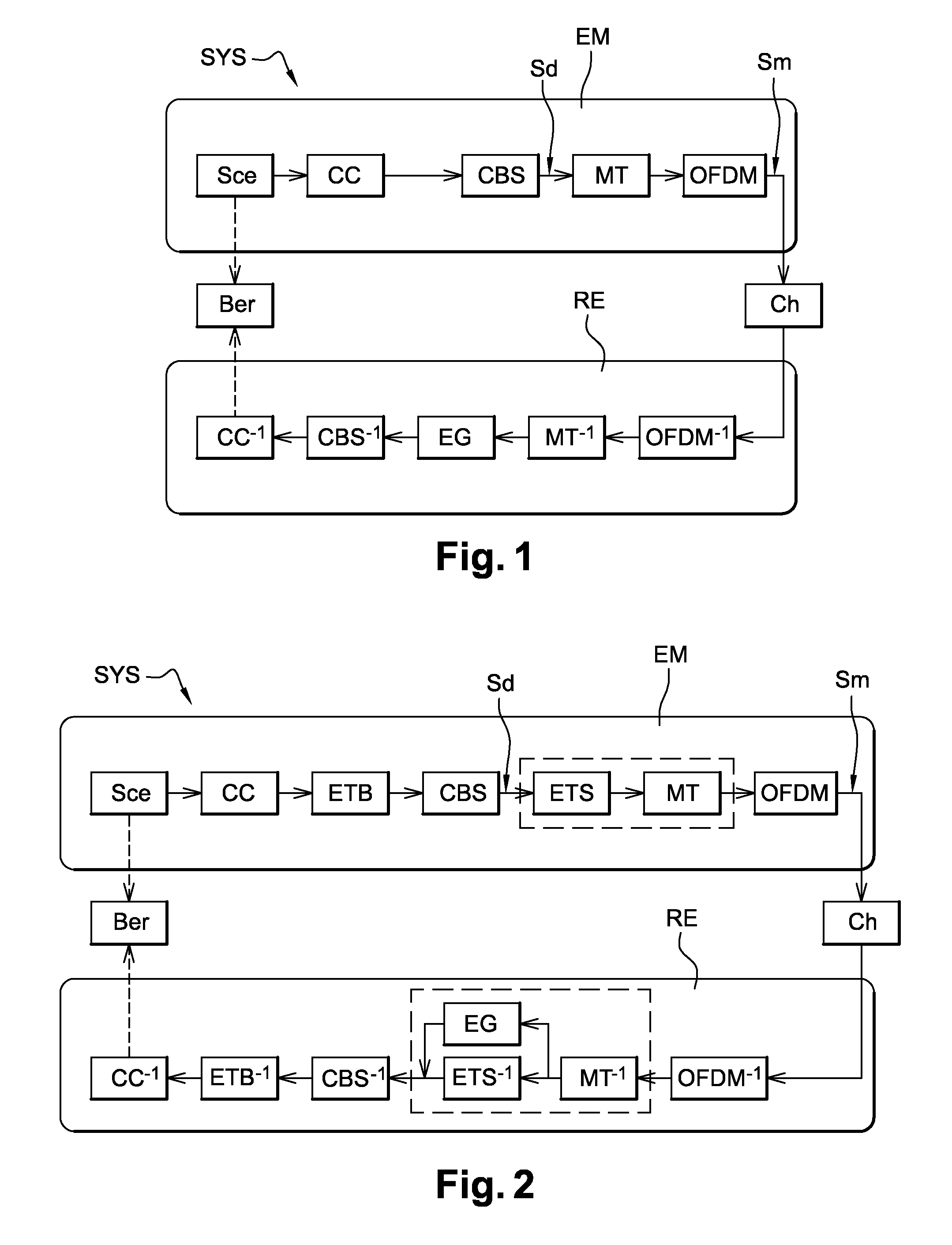
[0097]FIG. 1 shows a conventional transceiver system described in baseband for a prior art system SYS.

[0098]FIG. 2 shows a conventional transceiver system including interleaving ETB performed on the binary data and interleaving ETS performed on the data symbols Sd, described in baseband for a prior art system SYS.

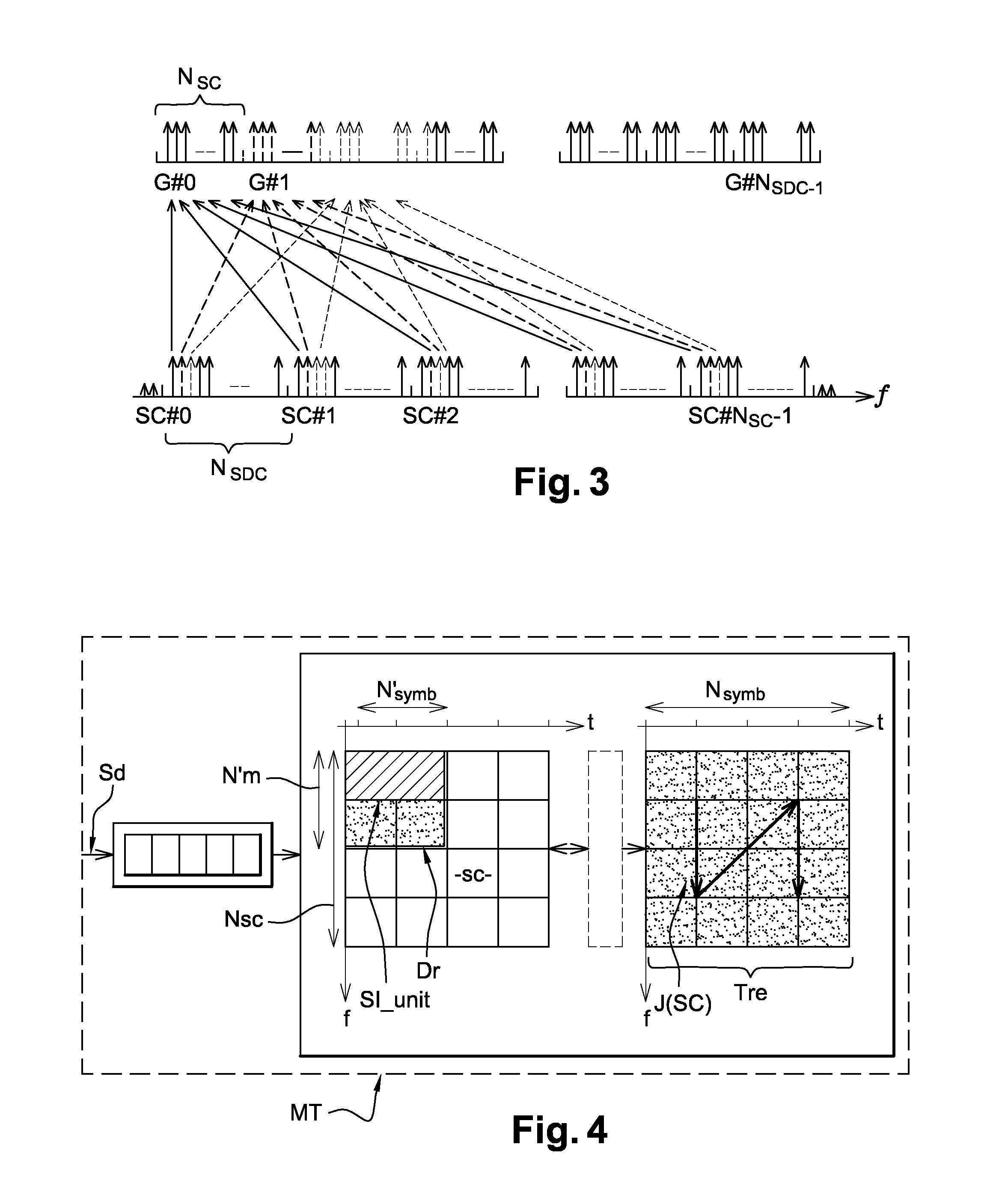
[0099]FIG. 3 is a diagram of a prior art mapping technique consisting in scattering a different symbol from each group of users to each sub-channel and in distributing the sub-channels in time and in frequency in such a manner as to mix different users within a given OFDM symbol.

[0100]FIGS. 4, 5, 6, and 7 relate to a prior art system complying with the standard IEEE 802.16e.

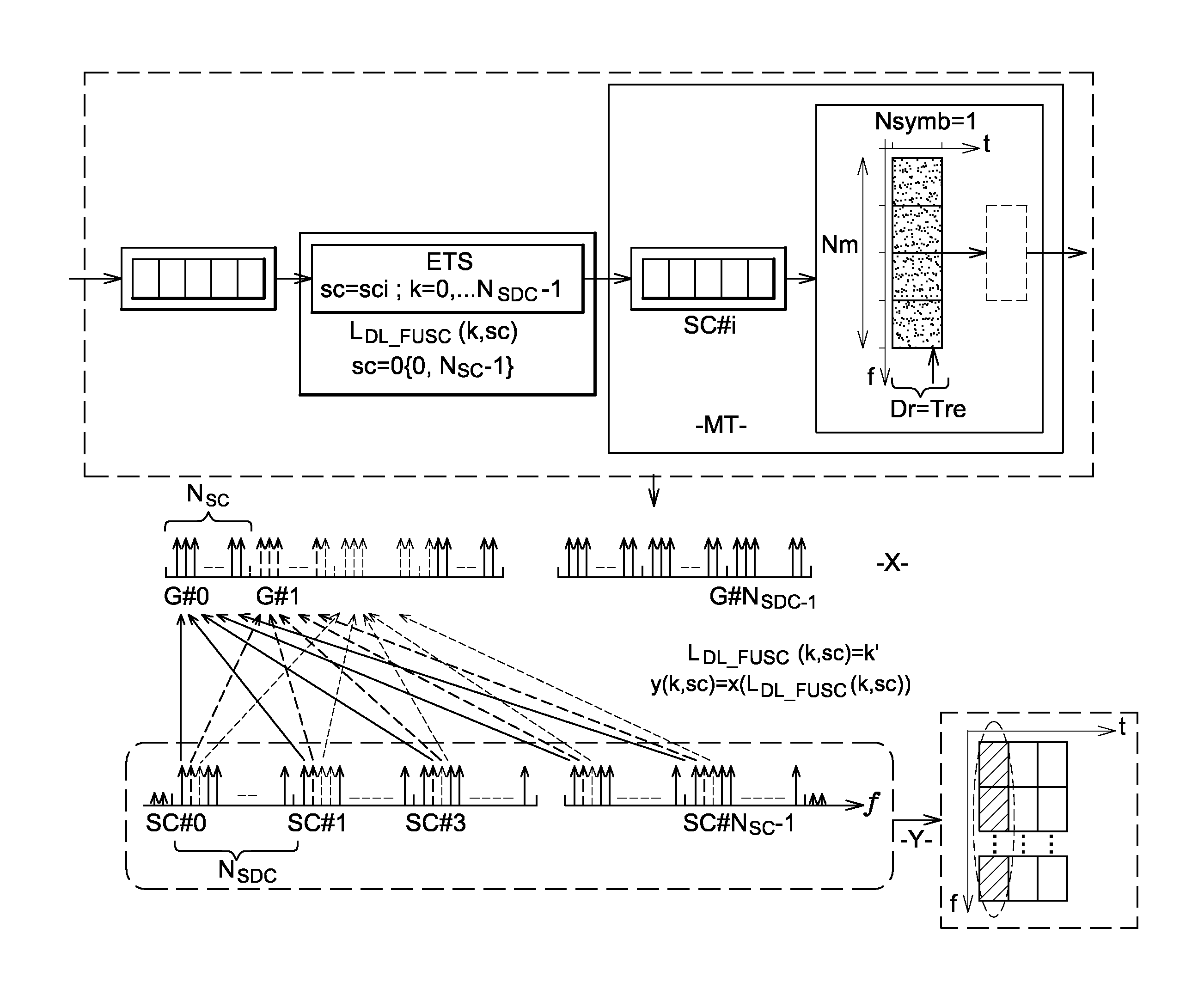
[0101]FIG. 4 is a diagram of the mapping method.

[0102]FIG. 5 is a detail diagram of the mapping method for FUSC mode for the down pat...


PUM


Abstract

A method is provided for mapping data symbols at the input of a multi-carrier modulator, which data symbols are interleaved in blocks of K symbols, into sub-channels of size equal to NSDC consecutive carriers scattered to one or more multi-carrier symbols, NSDC being a sub-multiple of K. The size NSDC of the sub-channels is determined as a function of a symbol interleaving pattern diversity between sub-channels.

Description

CROSS-REFERENCE TO RELATED APPLICATIONS[0001]This application is the U.S. national phase of the International Patent Application No. PCT / FR2010 / 050584 filed Mar. 30, 2010, which claims the benefit of French Application No. 09 52074 filed Mar. 31, 2009, the entire content of which is incorporated herein by reference.FIELD OF THE INVENTION[0002]The present invention relates to the field of telecommunications. Within this field, the invention relates more particularly to so-called “digital” communications. Digital communications comprise in particular wireless communications; but, for example, they also include wired communications. A communications transmission medium is commonly referred to as a transmission or propagation channel, originally as a reference to a channel over the air and by extension with reference to any channel.BACKGROUND[0003]The invention relates to techniques of mapping symbols in sub-channels distributed over one or more multi-carrier symbols, typically orthogon...

Claims


Application Information

Patent Timeline
Patent Type & Authority Patents(United States)
IPC IPC(8): H04W72/04
CPCH04L1/0071H04L5/0007H04L5/0037H04L5/0044H04L27/2608H04L27/2628H04L27/2613H04L27/26H04L25/03H03M13/27
Inventor SIAUD, ISABELLE
Owner ORANGE SA (FR)
Why Eureka
Try Eureka