Method for urea decomposition and ammonia feed to a selective catalytic reduction system

a catalytic reduction and ammonia feed technology, applied in the direction of separation process, dispersed particle separation, chemical apparatus and processes, etc., can solve the problems of nox emissions from small industrial, commercial and electric utility boilers and other lean burn stationary combustion sources, yamaguchi does not address the time required for complete decomposition and gasification of an aqueous solution of urea, and the use of steam from a boiler has a penalty, so as to reduce the cost of supplemental power

Active Publication Date: 2014-08-26
CECO ENVIRONMENTAL IP INC
View PDF20 Cites 12 Cited by
  • Summary
  • Abstract
  • Description
  • Claims
  • Application Information

AI Technical Summary

Benefits of technology

[0018]When the exhaust gas slipstream is above 750° F., cooling air, water injection or cooler downstream exhaust gas can be added to the slipstream to lower the gas temperature to the blower to less than 750° F. This reduces the cost of blower materials of construction and improves blower reliability.
[0022]The urea injection rate into the injection portion of the duct is programmed into a programmable logic controller (PLC) along with a boiler load signal, fuel flow rate, steam flow rate, exhaust gas flow rate, and / or NOx or ammonia slip signal to adjust the injection rate. The PLC controls the pulse width or on-time of the valve in the solenoid actuated injector which regulates the rate of urea injection.
[0026]The use of an exhaust gas slipstream as a transport medium helps reduce the cost of supplemental power for a heater or fuel for a burner, although ambient air or preheated air can also be used. An exhaust gas slipstream from a natural gas fired combustor is ideal in that it does not contain particulates from combustion. When solid fuels or heavy liquid fuels or waste gases are fired in a boiler or combustor it is preferred that the exhaust gas slipstream be filtered to reduce particulates through the decomposition duct and ammonia injection grid (“AIG”).

Problems solved by technology

The reduction of nitrogen oxide (“NOx”) emissions from small industrial, commercial and electric utility boilers and other lean burn stationary combustion sources continues to be a challenge.
For aqueous based solutions of ammonia, Yamaguchi suggests that 0.5-1.0 seconds are required to vaporize the ammonia solution and Yamaguchi does not address the time required for complete decomposition and gasification of an aqueous solution of urea.
However, the use of steam from a boiler has a penalty associated with removing steam from the heat or power generation process and also with the cost of preparing de mineralized boiler makeup water to replace the steam used in the vaporization of the aqueous ammonia or its precursor.
Peter-Hoblyn et al. suggest that for SCR, especially at high loads, it is sometimes practical to introduce the aqueous solution of NOx reducing reagent into a slip stream (less than all, e.g., 5-25%) of the exhaust gases to achieve gasification of the reagent prior to mixing with the major or entire portion of exhaust gases.
Peter-Hoblyn et al., however, do not describe how to prevent plugging of the compact pyrolysis chamber with urea decomposition products, especially at higher urea injection rates.
Additionally, it is difficult to see how complete gasification of urea is accomplished in the pyrolysis chamber described by Peter-Hoblyn et al.
Obviously the overall combustor efficiency would be negatively affected if this large quantity of flue gas were bypassed around a heat exchanger.
Lin et al. teach that at high loads with high temperatures the bypass damper can be closed; however, at low loads with low gas temperatures Lin et al. do not describe how this large quantity of bypassed gas would efficiently be brought up to a temperature sufficient for urea gasification.
That can lead to incomplete decomposition of urea and / or to the need for the longer residence times as proposed by Sun et al.

Method used


Image

  • Method for urea decomposition and ammonia feed to a selective catalytic reduction system
  • Method for urea decomposition and ammonia feed to a selective catalytic reduction system
  • Method for urea decomposition and ammonia feed to a selective catalytic reduction system

Examples


example 1

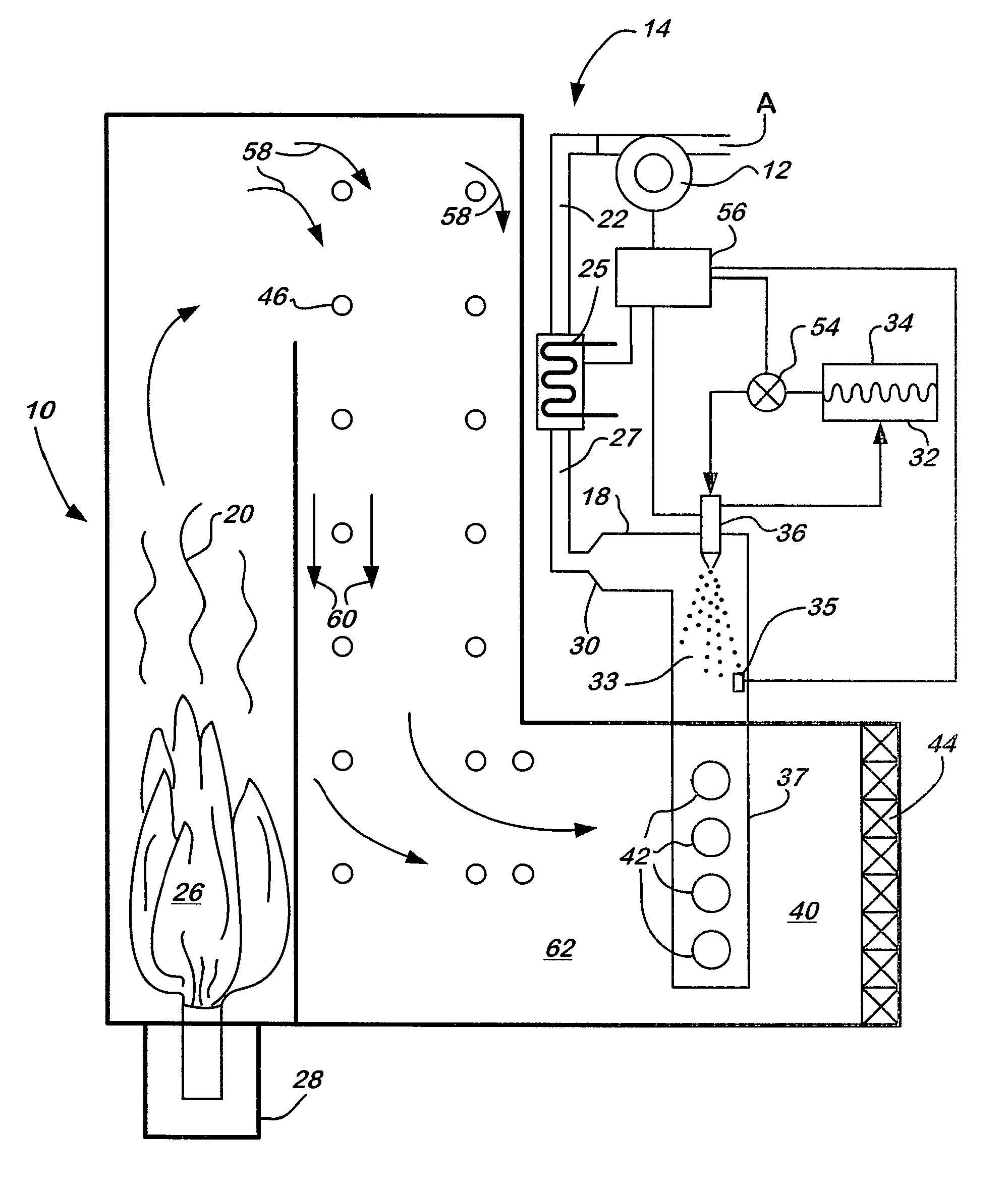
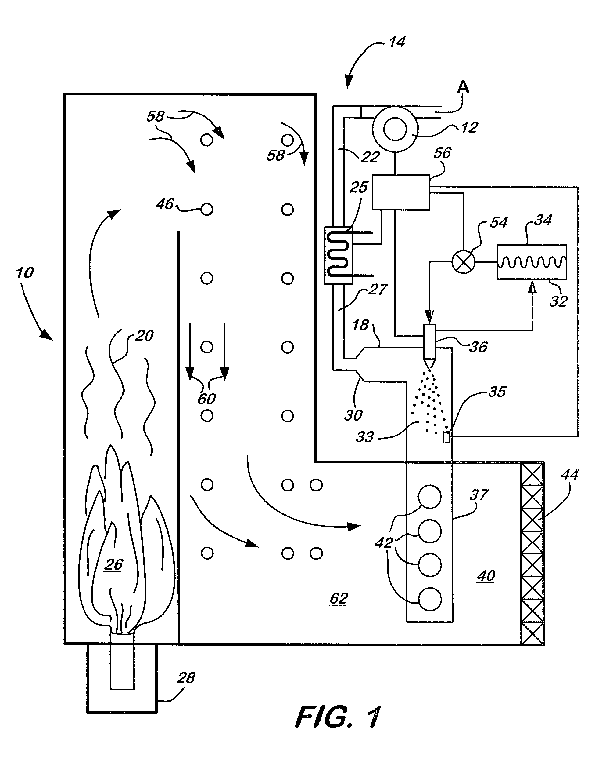
[0042]A slipstream of exhaust gas from a lean burn combustion engine is directed to an injection portion of a continuous duct. The slipstream flow rate is 300 scfm at a temperature of 700° F. to 750° F. The exhaust gas in the primary exhaust and in the slipstream contains 1100 ppm of NOx. The slipstream is connected to an injection portion (18) and a decomposition portion (33) of a continuous duct (14) that is 5″ in diameter. An aqueous solution of 32.5% urea is injected in the inlet end of the injection portion (18) of the continuous duct (14) using a solenoid actuated return flow injector as described in U.S. Pat. No. 7,467,749 to Tarabulski et al., the contents of which is hereby incorporated by reference herein. A computer based TRIM-NOX® injection system as commercially available through Combustion Components Associates Inc. with an injection pump, filter, day tank, pressure sensor and touch screen display is used to inject the aqueous reagent at a rate of 0.5 to 0.75 gallons / h...

example 2

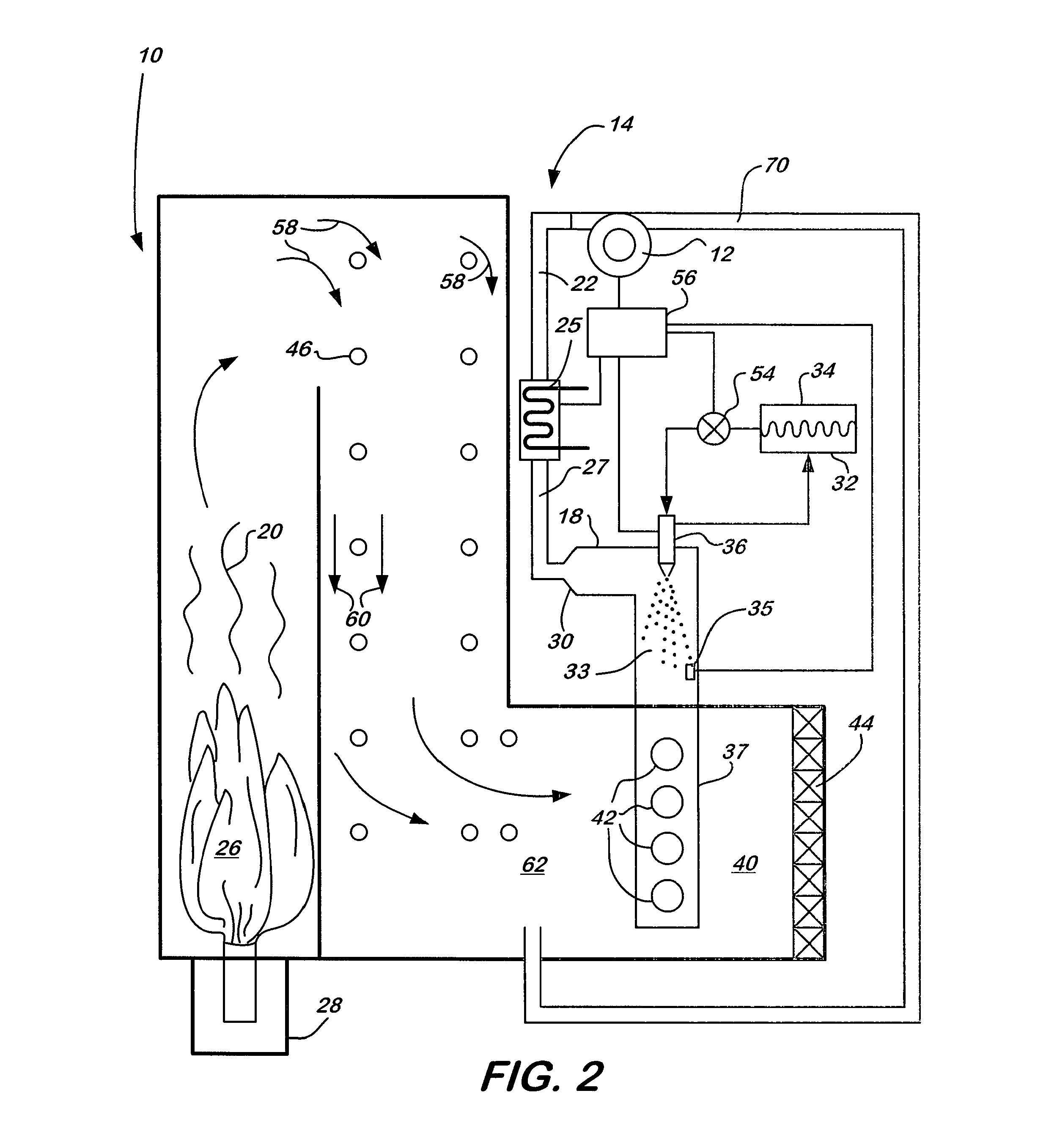
[0045]A fan is used to supply ambient air to a 60 Kw electric heater. The fan and heater deliver 300 scfm of air at a temperature of 700° F. to 750° F. to a 5″ diameter continuous duct having an injection portion (18) and a decomposition portion (33). A 32.5% solution of aqueous urea reagent is injected into the injection portion (18) of the continuous duct (14) using a solenoid actuated return flow injector and system as described in Example 1.

[0046]The outlet of the decomposition portion (33) of the continuous duct (14) is connected to the AIG (37) and catalyst (44) arrangement as described in Example 1. The full exhaust flow from a lean burn combustion engine is passed through the catalyst reactor at a rate of 1100 scfm to 1200 scfm and a temperature of 750 F with a NOx concentration of 1100 ppm. Injection of 0.5 to 0.75 gph of aqueous solution into the injection portion (18) of the continuous duct (14) reduces the NOx out of the SCR reactor to 100 ppm indicating that the urea re...


PUM

PropertyMeasurementUnit
temperatureaaaaaaaaaa
residence timeaaaaaaaaaa

Abstract

A method of reducing NOx emissions from a lean burn combustion source employs an aqueous solution of reagent that is injected into a continuous decomposition duct at a rate of 0.2-10 gph with a flowing side stream of hot gas at a rate of 150-3000 scfm and a temperature of greater than 700° F. in the decomposition duct such that the aqueous reagent is converted to ammonia gas that is conveyed by the continuous decomposition duct to an ammonia injection grid that is placed in a primary exhaust stream from the combustion source upstream of a NOx reducing catalyst and NOx is reduced.

Description

CROSS-REFERENCE TO RELATED APPLICATIONS[0001]The present application claims the benefit under 35 U.S.C. §119(e) of the U.S. Provisional Patent Application Ser. No. 61 / 710,356, filed on Oct. 5, 2012.FIELD OF THE INVENTION[0002]The present invention relates generally to the reduction of nitrogen oxide (NOx) emissions from small industrial, commercial and electric utility boilers and other lean burn stationary combustion sources. More particularly, the present invention relates to a system and method in which urea is converted to ammonia for use in NOx reduction by selective catalytic reduction (SCR).BACKGROUND OF THE INVENTION[0003]The reduction of nitrogen oxide (“NOx”) emissions from small industrial, commercial and electric utility boilers and other lean burn stationary combustion sources continues to be a challenge. Primary measures, such as low NOx burners, flue gas recirculation, fuel staging or air staging, need to balance the impact on the efficiency and stability of combustio...

Claims


Application Information

Patent Timeline
Patent Type & Authority Patents(United States)
IPC IPC(8): B01D53/56
CPCB01D53/565B01D2251/2067B01D53/90B01D53/8631
Inventor BRODERICK, JEFFREY MICHAELLINDEMANN, SCOTT H.VALENTINE, JAMES M.
Owner CECO ENVIRONMENTAL IP INC
Why Eureka
Try Eureka