Acoustic panel

Active Publication Date: 2014-09-02
THE BOEING CO
View PDF36 Cites 48 Cited by
  • Summary
  • Abstract
  • Description
  • Claims
  • Application Information

AI Technical Summary

Benefits of technology

[0007]The disclosed embodiments provide an acoustic panel capable of attenuating sound over a relatively wide range of frequencies and engine operating conditions which induce a wide range of sound pressure levels. The acoustic panel employs a septumized core and a perforated, linear acoustic facesheet which respectively provide separate impedance and dampening functions. More specifically, the primary impedance function is moved toward in the flow of acoustic waves s

Problems solved by technology

High bypass type aircraft engines produce noise due to the high airflows through inlets, rotating stages and exhaust nozzles of the engines.
In some acoustic panels, only a septum in the core is used to dampen incoming acoustic waves, but the

Method used


Image

  • Acoustic panel
  • Acoustic panel
  • Acoustic panel

Examples


Example

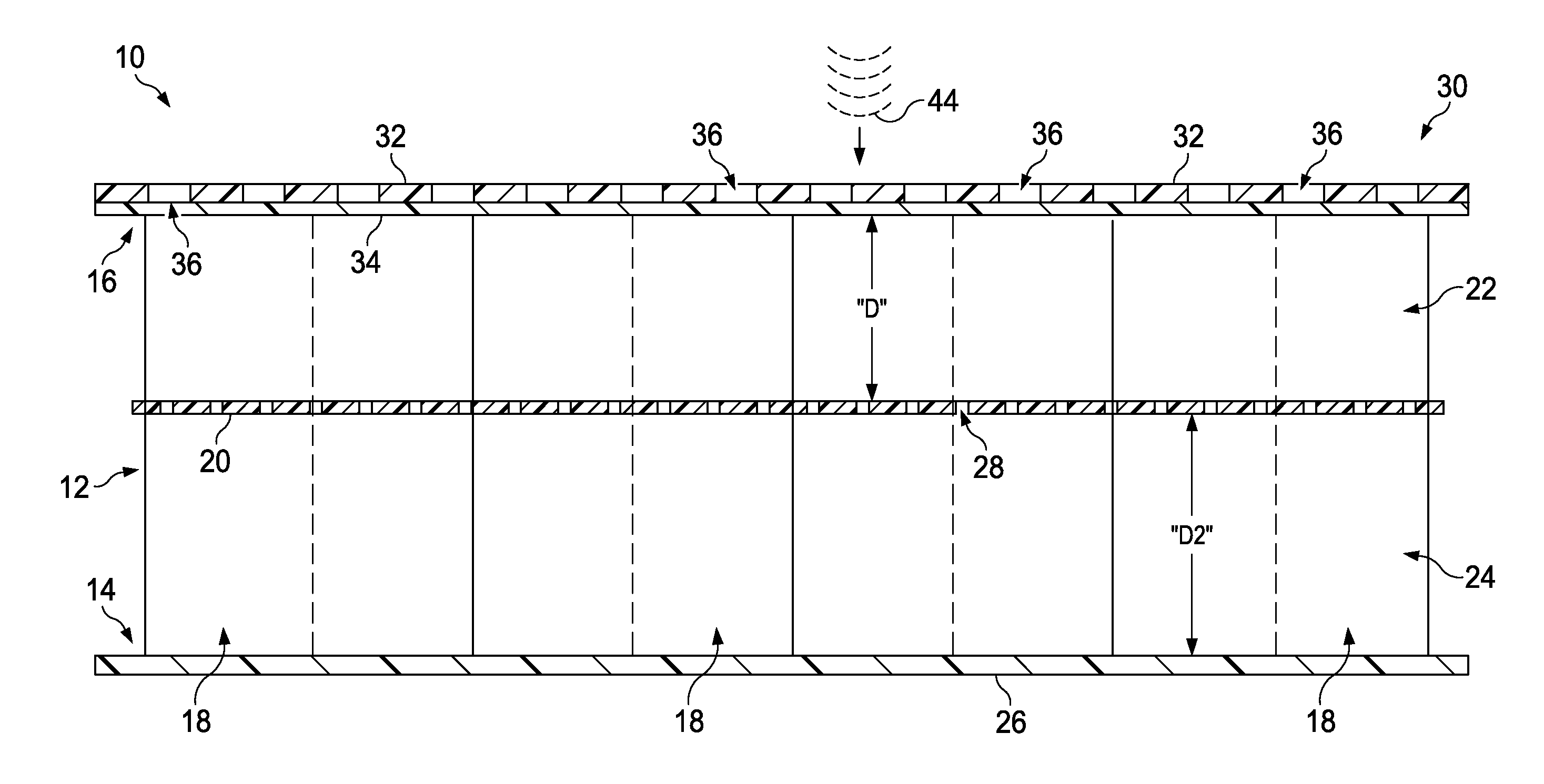
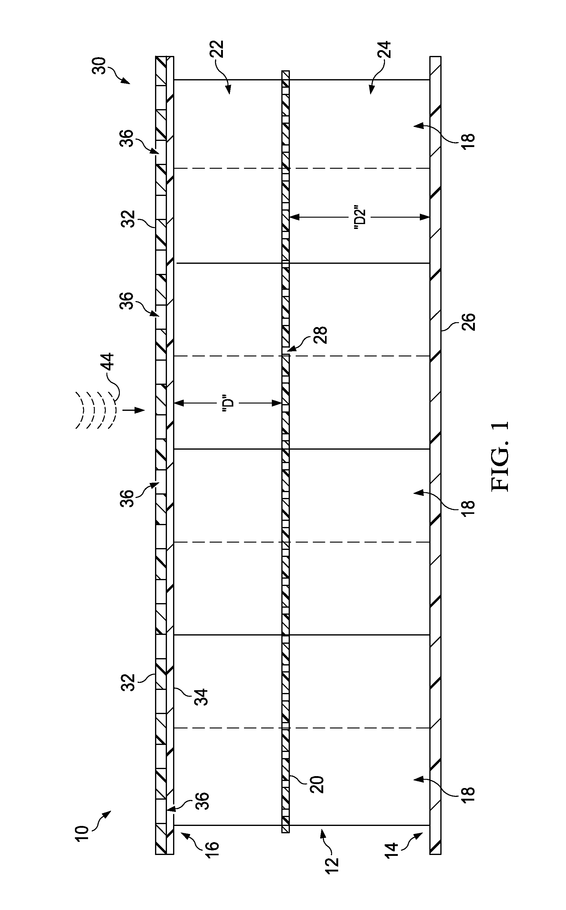
[0022]FIG. 1 illustrates one embodiment of an acoustic panel 10 for effectively attenuating sound over a relatively wide range of frequencies and sound pressure levels. One side of the panel 10 is exposed to the sound, hereinafter sometimes referred to as acoustic waves 44. The acoustic panel 10 includes a single layer of cellular hexagonal core 12 (or other type of core to provide a local air column) having a first side 14, a second opposite side 16, and a plurality of individual cells 18 extending therebetween. The sizes of cells 18 can be selected to tune core 12 to acoustic waves having a particular frequency or range of frequencies. For example, and without limitation, the core 12 may be tuned to a frequency range of between approximately 800 Hz and 4,000 Hz. While the cells 18 of the illustrated core 12 have a hexagonal cross-sectional shape, the cells 18 may have other cross-sectional shapes enabling the acoustic panel 10 to attenuate sound and noise over a desired range of f...


PUM


Abstract

An acoustic panel for sound attenuation employs a septumized cellular core sandwiched between a backsheet and a linear acoustic facesheet. The linear acoustic facesheet employs a linear material layer that impedes acoustic waves entering the core substantially linearly over a wide range of frequencies and sound of pressure levels.

Description

BACKGROUND INFORMATION[0001]1. Field[0002]The present disclosure generally relates to acoustic treatments for controlling sound and noise, and deals more particularly with an acoustic panel fused for sound attenuation.[0003]2. Background[0004]High bypass type aircraft engines produce noise due to the high airflows through inlets, rotating stages and exhaust nozzles of the engines. In order to reduce noise and satisfy noise regulations governing commercial aircraft, high bypass engines may incorporate acoustic panels in various parts of the engine, such as in the inlets of engine nacelles. These acoustic panels, sometimes referred to as acoustic treatments or acoustic liners, may comprise a septumized honeycomb core sandwiched between a perforated inner skin and a non-perforated outer skin. The placement of septums in the cells of the honeycomb core form cavities that act as Helmholtz resonators which attenuate the sound / noise caused by high speed airflow into the inlets of the engin...

Claims


Application Information

Patent Timeline
IPC IPC(8): E04B1/82
CPCE04B1/82F02K1/827G10K11/168G10K11/00F02C7/045G10K11/172Y02T50/672Y02T50/60
Inventor HERRERA, ERICNESBITT, ERIC H.
Owner THE BOEING CO
Why Eureka
Try Eureka