Selective soldering using fiber optic device

a fiber optic device and selective soldering technology, applied in the direction of soldering apparatus, instruments, manufacturing tools, etc., can solve the problems of reduced size of electrical components, soldering problems, and most computing systems are not operational

Active Publication Date: 2014-09-02
WESTERN DIGITAL TECH INC
View PDF10 Cites 2 Cited by
  • Summary
  • Abstract
  • Description
  • Claims
  • Application Information

AI Technical Summary

Problems solved by technology

In fact, most computing systems are not operational without some type of HDD to store the most basic computing information such as the boot operation, the operating system, the applications, and the like.
Some of the electrical components of the HDD require solder connections and in some cases, the reduced size of the electrical components leads to problems with soldering such as substrate damage.

Method used


Image

  • Selective soldering using fiber optic device
  • Selective soldering using fiber optic device
  • Selective soldering using fiber optic device

Examples


Embodiment Construction

[0013]Reference will now be made in detail to the alternative embodiment(s) of the present invention. While the invention will be described in conjunction with the alternative embodiment(s), it will be understood that they are not intended to limit the invention to these embodiments. On the contrary, the invention is intended to cover alternatives, modifications and equivalents, which may be included within the spirit and scope of the invention as defined by the appended claims.

[0014]Furthermore, in the following detailed description of the present invention, numerous specific details are set forth in order to provide a thorough understanding of the present invention. However, it will be recognized by one of ordinary skill in the art that the present invention may be practiced without these specific details. In other instances, well known methods, procedures, components, and circuits have not been described in detail as not to unnecessarily obscure aspects of the present invention.

[...


PUM

PropertyMeasurementUnit
shapeaaaaaaaaaa
speedaaaaaaaaaa
sizeaaaaaaaaaa

Abstract

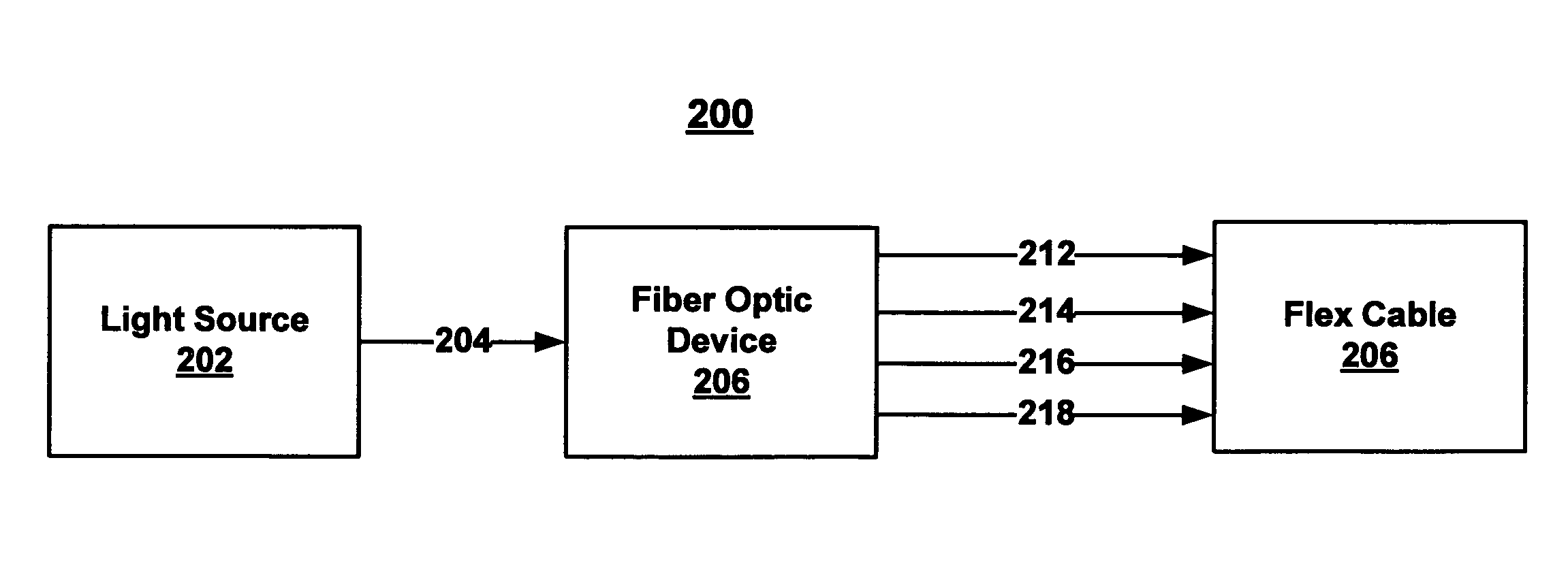
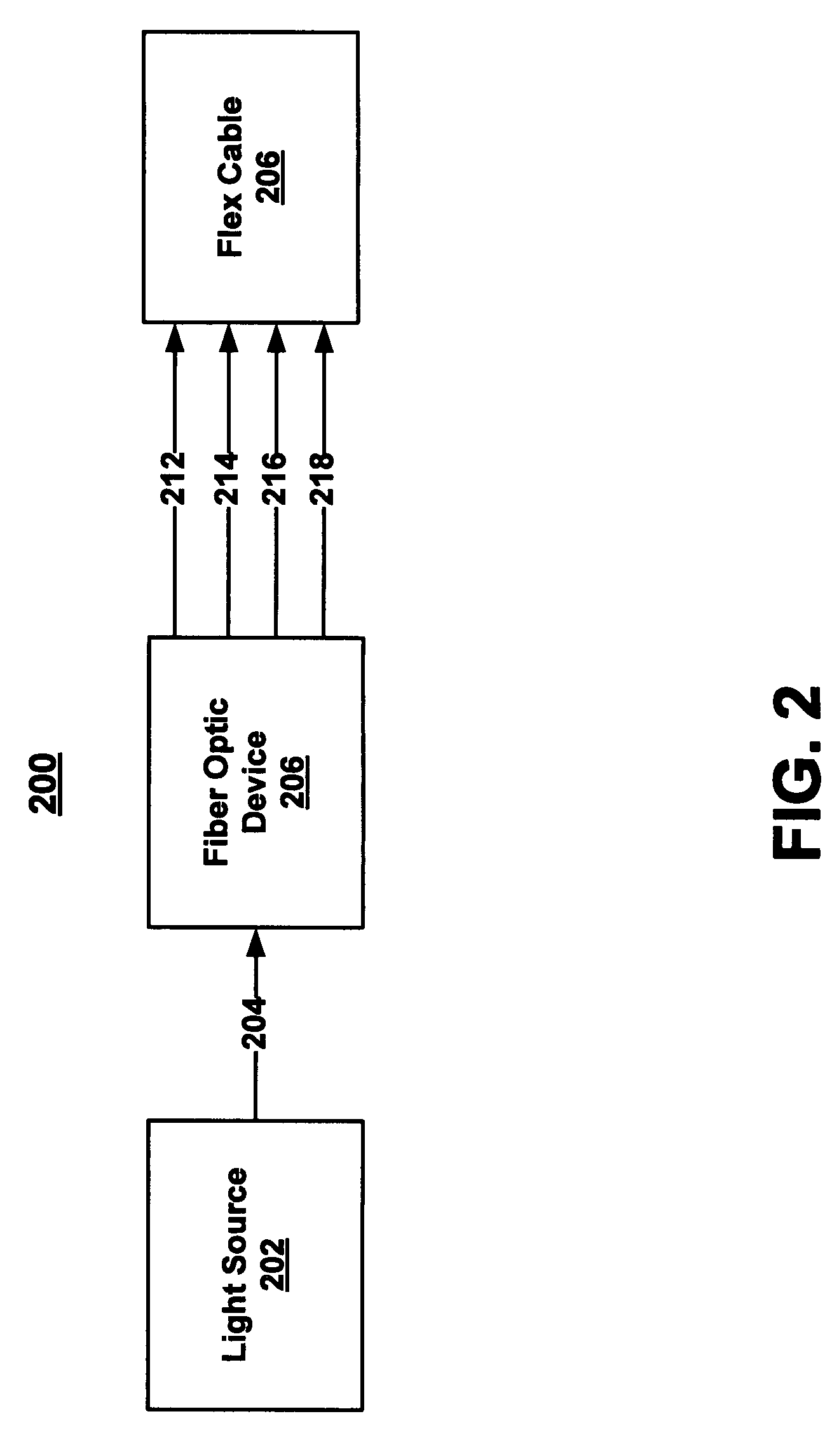
A fiber optic device for enabling soldering is described. The fiber optic device includes an entry portion comprising an optical fiber bundle for receiving a single light beam wherein the optical fiber bundle splits the light beam into a plurality of separate portions, each of the separate portions for enabling soldering. The fiber optic device further includes an exit portion for emitting each of the plurality of separate portions of the light beam in a pattern to enable soldering at a plurality of locations simultaneously utilizing the single light beam.

Description

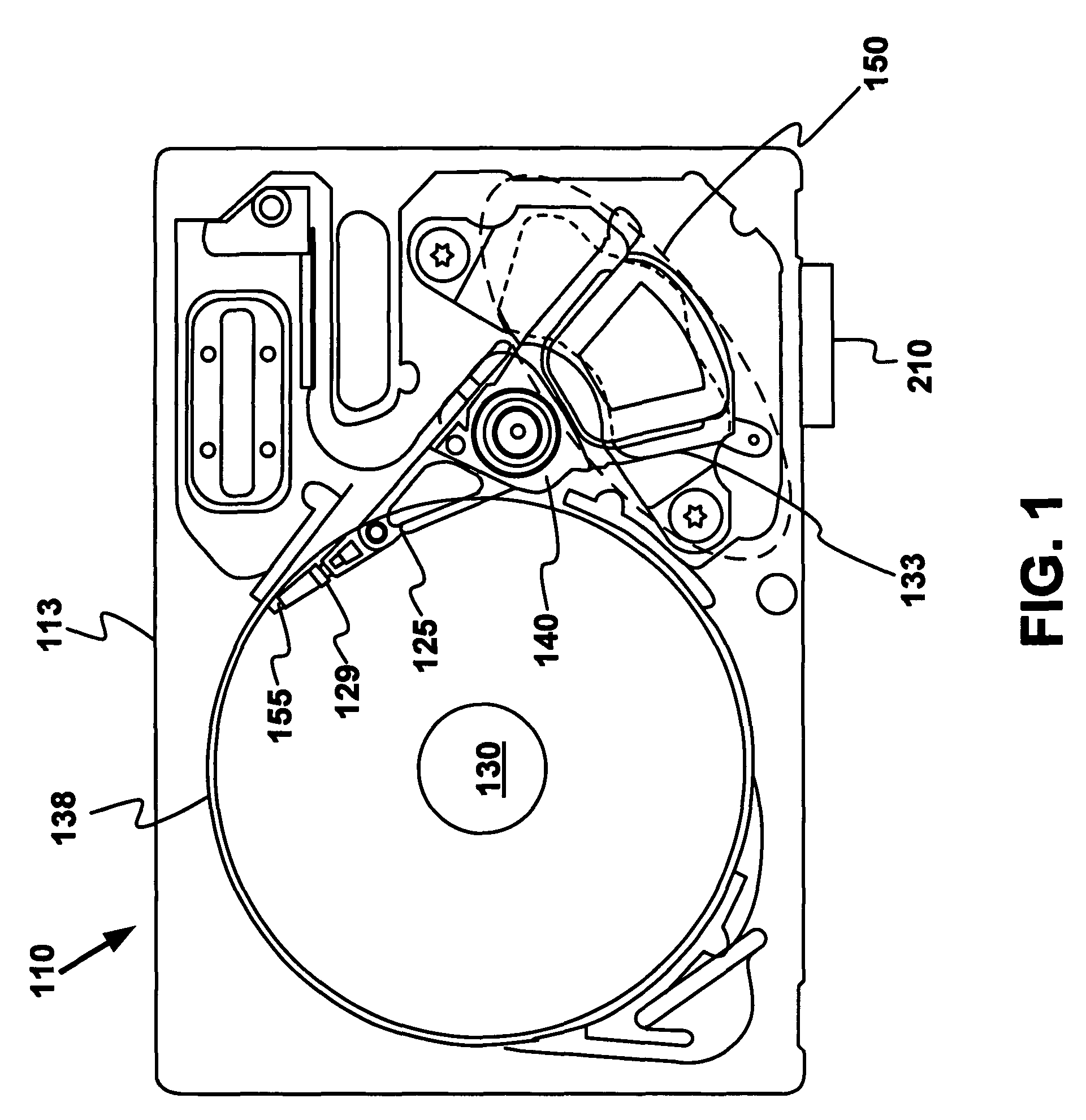
TECHNICAL FIELD[0001]The present invention relates to the field of hard disk drive development, and more particularly to a method and system for soldering a flex cable of a hard disk drive.BACKGROUND ART[0002]Hard disk drives (HDD) are used in almost all computer system operations. In fact, most computing systems are not operational without some type of HDD to store the most basic computing information such as the boot operation, the operating system, the applications, and the like. In general, the HDD is a device which may or may not be removable, but without which the computing system will generally not operate.[0003]In operation, the hard disk is rotated at a set speed via a spindle motor assembly having a central drive hub. There are tracks at known intervals across the disk. When a request for a read of a specific portion or track is received, the HDD aligns a read / write head, via an arm, over the specific track location and the head reads the information from the disk. In the ...

Claims


Application Information

Patent Timeline
Patent Type & Authority Patents(United States)
IPC IPC(8): B23K26/00
CPCG02B6/04B23K1/0016B23K1/0056B23K26/067B23K26/0676B23K2201/36G11B5/4853B23K2101/36
Inventor FENG, XIANGYANG
Owner WESTERN DIGITAL TECH INC
Why Eureka
Try Eureka