Pressure regulating valve for regulating the pressure in a high-pressure reservoir

a technology of pressure regulating valve and high-pressure reservoir, which is applied in the direction of fluid pressure control, process and machine control, etc., can solve the problems of unattainable emergency operation function (so-called limp home functionality), engine or motor will no longer work, and the pressure in the rail cannot be built up. , to achieve the effect of avoiding component damage and danger to humans and the environment, avoiding weak springs and avoiding emergency operation functions

Inactive Publication Date: 2014-09-09
ROBERT BOSCH GMBH
View PDF17 Cites 4 Cited by
  • Summary
  • Abstract
  • Description
  • Claims
  • Application Information

AI Technical Summary

Benefits of technology

[0015]Because two oppositely acting magnet devices in conjunction with a weaker spring are used, instead of one magnet device that closes the pressure regulating valve or its valve piston, the advantages of the two previously known types of pressure regulating valves can be combined with one another, without having to take their disadvantages into the bargain as well.
[0016]The mechanical opening pressure (currentless state) can preferably be in the medium pressure range of the system. The force of the first magnet device acts counter to the spring force, so that with the pressure regulating valve, rail pressures in the range from 0 bar up to the mechanical opening pressure of the spring can be regulated.
[0017]The force of the second magnet device reinforces the spring force. Thus rail pressures between the mechanical opening pressure of the spring up to the maximum system pressure can advantageously be regulated.
[0018]By means of an intelligent current control by means of the control and regulating device or control unit, a constant pressure rise / drop can be attained.
[0019]Even in the instances of “control unit failure” or “power supply failure”, the rail pressure remains within the operating range.
[0020]In an advantageous feature of the invention, it is provided that the magnet devices are embodied as magnet coils.
[0021]The embodiment according to the invention makes it possible to regulate pressure for common rail injection systems, especially in utility vehicles, within the entire regulating range in various modes of regulation. The embodiment of the invention likewise ensures a limp-home functionality of the utility vehicles, while the maximum system pressure does not rise beyond the allowable range.

Problems solved by technology

However, the disadvantage of this construction is that when there is a power loss, for instance from cable breakage caused by damage from martens, no further rail pressure can be built up, and the engine or motor will no longer work.
Hence an emergency operation function (so-called limp home functionality) is thus unattainable.
This can lead to component damage and can endanger humans and the environment.

Method used


Image

  • Pressure regulating valve for regulating the pressure in a high-pressure reservoir
  • Pressure regulating valve for regulating the pressure in a high-pressure reservoir
  • Pressure regulating valve for regulating the pressure in a high-pressure reservoir

Examples


Embodiment Construction

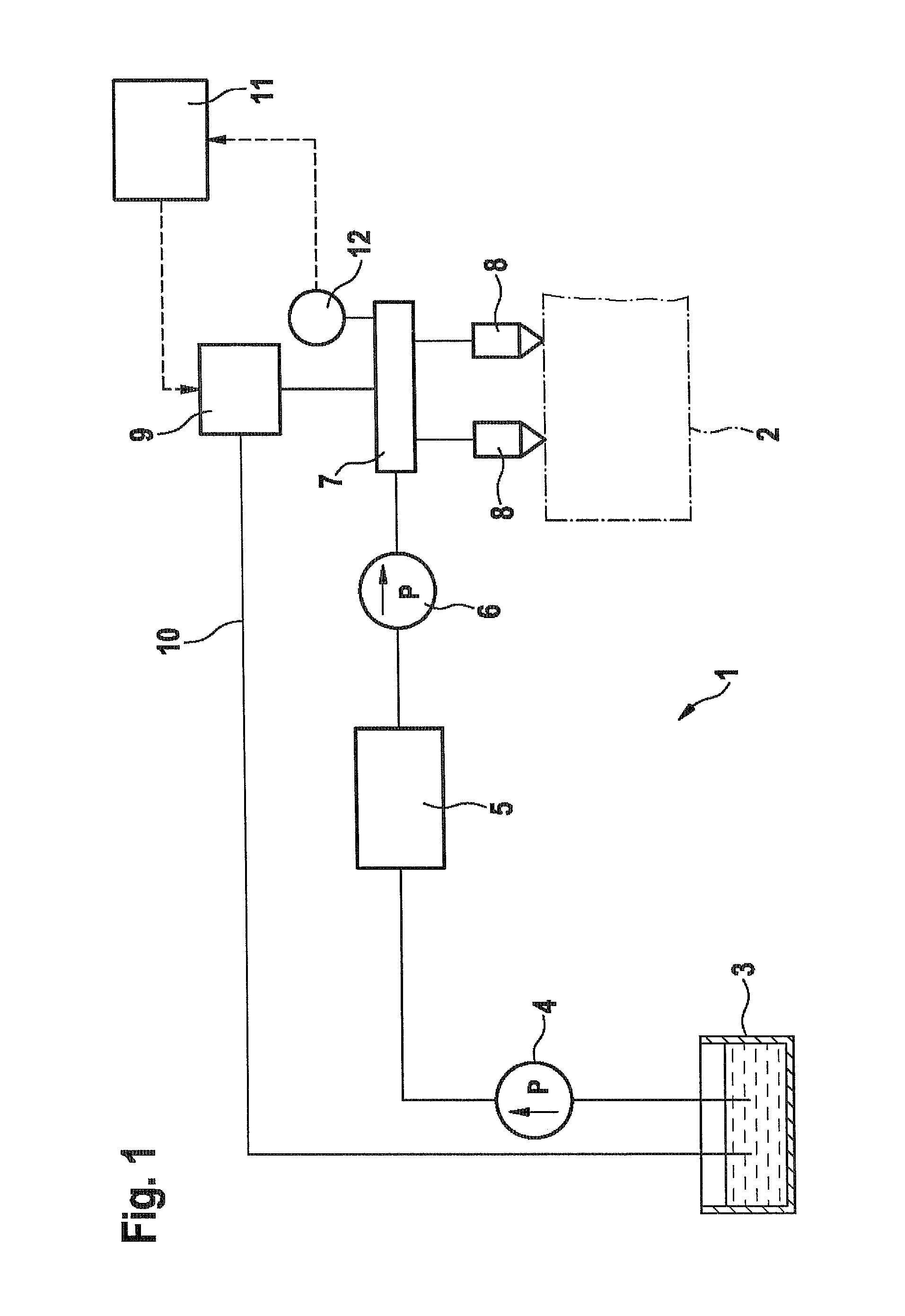
[0026]FIG. 1 shows a fuel system 1 that is used to supply an internal combustion engine 2. The engine 2 is indicated only schematically in FIG. 1 by a dot-dashed line.

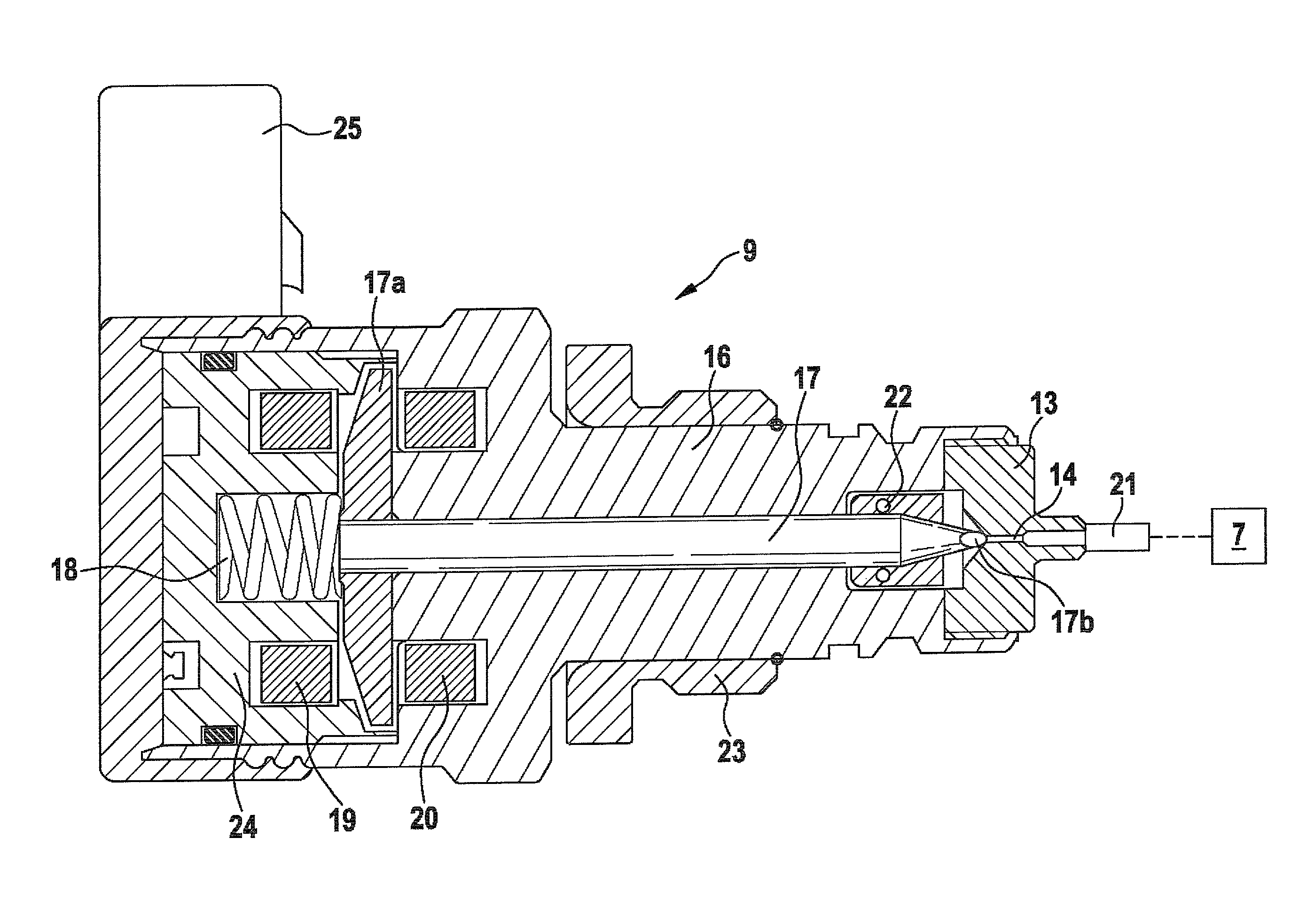
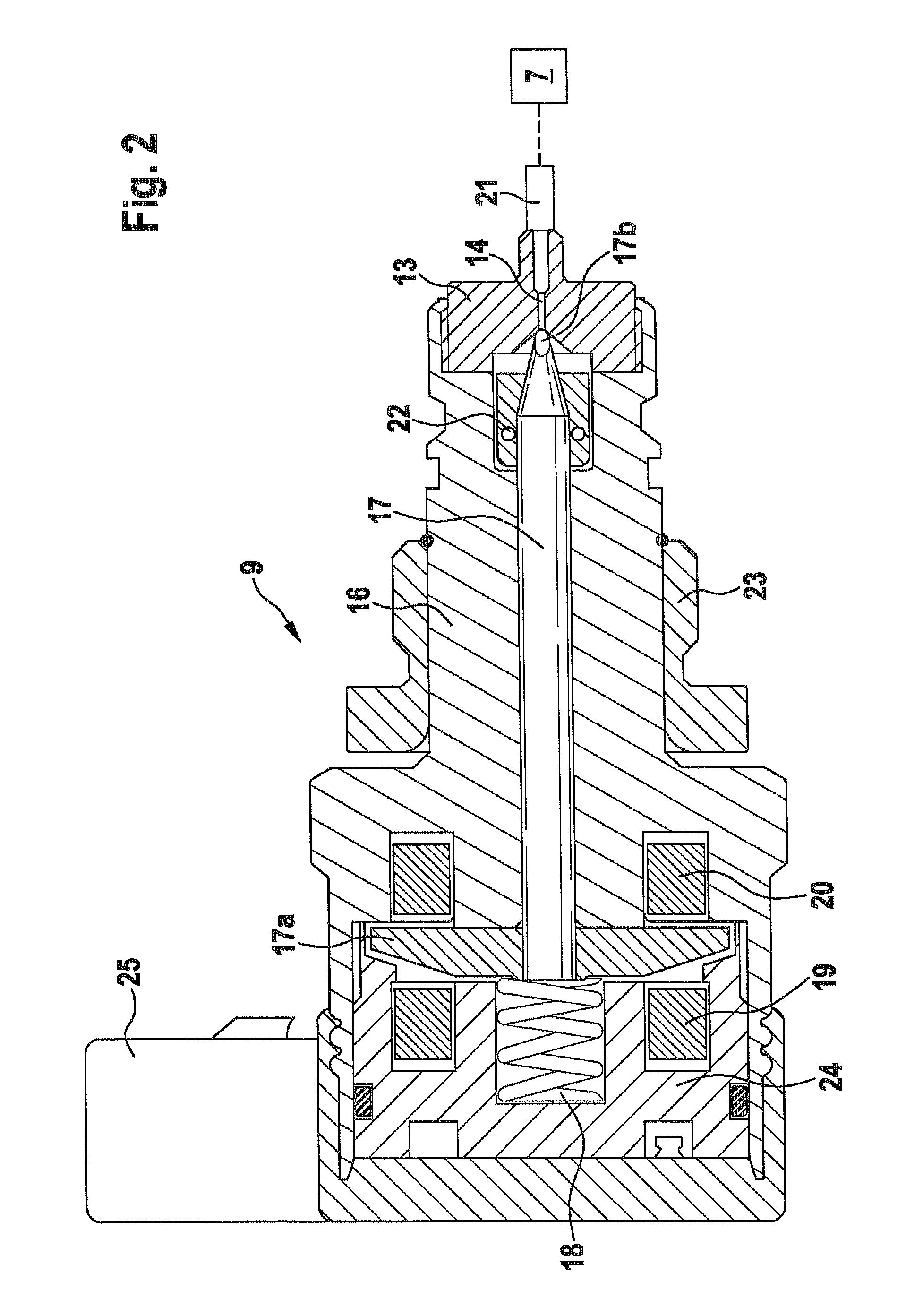
[0027]The fuel system 1 includes a fuel tank 3, from which a typically electrically operated feed pump 4 pumps the fuel to an adjusting device 5, which is also called a metering unit. From the adjusting device 5, the fuel is pumped to a high-pressure fuel pump 6 driven mechanically by the engine 2. The high-pressure fuel pump 6 compresses the fuel to a very high pressure and pumps it into a high-pressure reservoir 7, also known as a “rail”. A plurality of injectors 8 are connected to the high-pressure reservoir 7 and inject the fuel into combustion chambers, not shown, of the engine 2. A pressure regulating valve 9 of the invention is connected to the high-pressure reservoir 7 and will be described in detail below in conjunction with FIG. 2. From the pressure regulating valve 9, a diversion line 10 leads back to the fu...


PUM


Abstract

The invention relates to a machine tool having working field illumination disposed in a housing, having an illumination mechanism and a transparent element which allows the light from the illumination mechanism to be led out toward the working field. A light beam can be deflected between the illumination mechanism and the transparent element. According to the invention, the transparent element forms a region of the housing.

Description

CROSS-REFERENCE TO RELATED APPLICATION[0001]This application is a 35 USC 371 application of PCT / EP2008 / 066054 filed on Nov. 24, 2008.BACKGROUND OF THE INVENTION[0002]1. Field of the Invention[0003]The invention relates to a pressure regulating valve for regulating the pressure in a high-pressure reservoir of an internal combustion engine, in particular in common rail injection systems.[0004]The invention also relates to a fuel system of an internal combustion engine, in particular of a common rail injection system, as generically defined by the preamble to claim 10.[0005]2. Description of the Prior Art[0006]From German Patent Disclosure DE 10 2005 052 636 A1, a fuel system is known which includes a feed pump that feeds fuel from a fuel tank. From the feed pump, via an adjusting device called a metering unit, the fuel reaches a high-pressure fuel pump, which compresses the fuel and supplies a high-pressure reservoir (“rail”). A plurality of fuel injectors are connected to the high-pr...

Claims


Application Information

Patent Timeline
Patent Type & Authority Patents(United States)
IPC IPC(8): F02M69/54F02M59/36F02M63/00F02M63/02F16K31/06G05D16/20
CPCF02M63/025F02M63/026F02M63/0015F16K31/0665G05D16/2013F16K31/0679F02M63/0063F02M63/0052F02M63/0036G05D16/2022
Inventor ROTH, BRIGITTE
Owner ROBERT BOSCH GMBH
Why Eureka
Try Eureka