Methods and apparatus with improved ventilatory support cycling

a technology of ventilator support and cycling support, which is applied in the direction of mechanical equipment, valves, operating means/releasing devices, etc., can solve the problems of improper pressure change, device discomfort for patients, and prominent cycling issue,

Active Publication Date: 2014-09-09
RESMED LTD
View PDF13 Cites 11 Cited by
  • Summary
  • Abstract
  • Description
  • Claims
  • Application Information

AI Technical Summary

Benefits of technology

[0010]In the invention, a synchronization threshold is calculated that is compared to a measure of flow for purposes of determining whether the ventilator should advance from inspiration to expiration. In a preferred embodiment, the threshold is a function of time that permits it to change within a single inspiratory cycle from a less sensitive threshold during early portions of the cycle to a more sensitive threshold during latter portions of the cycle. In one embodiment of the invention, the threshold is provided with a refractory period to prevent a transition to expiration during certain times within a cycle when such a transition is not desired or unlikely to accurately reflect the patient's actual advance to expiration. Additional aspects of the invention are described in more detail in the following specification.

Problems solved by technology

Cycling becomes a prominent issue when respiratory mechanics are abnormal, especially in chronic obstructive pulmonary disease (COPD).
A goal of these processes for cycling is to make a ventilator device more comfortable for a user because if respiratory events are not properly synchronized, the device may be quite uncomfortable for a patient.
Current methods for cycling can sometimes improperly detect expiration and result in an improper pressure change.

Method used


Image

  • Methods and apparatus with improved ventilatory support cycling
  • Methods and apparatus with improved ventilatory support cycling
  • Methods and apparatus with improved ventilatory support cycling

Examples


Embodiment Construction

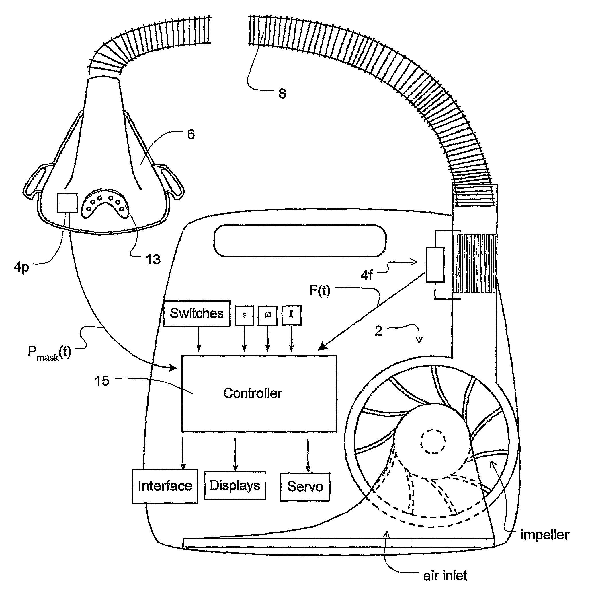
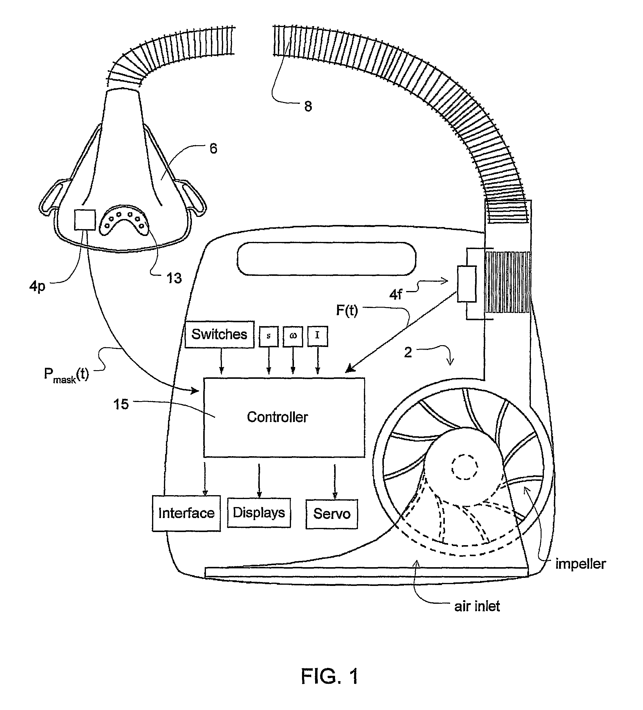
[0018]In reference to FIG. 1, the pressure delivery device includes a servo-controlled blower 2, a mask 6, and an air delivery conduit 8 for connection between the blower 2 and the mask 6. Exhaust gas is vented via exhaust 13. Optionally, a flow sensor 4f and / or pressure sensor 4p may also be utilized in which case mask flow may be measured using a pneumotachograph and differential pressure transducer or similar device to derive a flow signal F(t), and mask pressure is measured at a pressure tap using a pressure transducer to derive a pressure signal Pmask(t). The pressure sensor 4f and flow sensor 4p have only been shown symbolically in FIG. 1 since it is understood that those skilled in the art would understand how to measure flow and pressure. Flow F(t) and pressure Pmask(t) signals are sent to a controller or microprocessor 15 to derive a pressure request signal Prequest(t). Alternatively, a flow signal f(t) and pressure signal Pmask(t) may be estimated or calculated in relation...


PUM


Abstract

A ventilator that delivers air at different pressures to a patient during inspiratory and expiratory cycles of breathing and that cycles from inspiratory to expiratory operation when the patient's respiratory flow passes a threshold level. The threshold generally increases from the beginning of inspiration to the end of inspiration. The increase can be linear over all or only a portion of the inspiratory cycle, and the threshold can be adjusted so that cycling is prevented during the initial portion of an inspiratory cycle. The minimum and maximum levels may both be functions of peak flow and the threshold may increase as a function of elapsed inspiratory time. The rate at which the threshold increases from a minimum level to a maximum level may be adjustable for individual patient needs and may be determined from previous breaths.

Description

CROSS-REFERENCES TO RELATED APPLICATIONS[0001]The present application is a national phase entry under 35 U.S.C. §371 of International Application No. PCT / AU2005 / 000895 filed Jun. 22, 2005, published in English on Jan. 5, 2006, as International Publication No. WO 2006 / 000017, which claims priority to U.S. Provisional Application No. 60 / 582,580 filed on Jun. 23, 2004, all of which are incorporated herein by reference.FIELD OF THE INVENTION[0002]The invention relates to methods and apparatus for the provision of ventilatory assistance synchronized with a subject's respiratory cycle. More specifically, the invention relates to methods for synchronizing the ventilator to cycle its pressure response in conjunction with the patient's respiration cycle.BACKGROUND OF THE INVENTION[0003]The present invention is applicable to any form of ventilation in which respiratory flow is used for cycling, although it is primarily useful in noninvasive pressure-support ventilation. The invention also fin...

Claims


Application Information

Patent Timeline
Patent Type & Authority Patents(United States)
IPC IPC(8): A61M16/00A62B7/00
CPCA61M16/0051A61M16/0069A61M2016/0021A61M2016/0039A61M16/0003A61M2016/0036A61M2205/3303A61M16/024A61M16/06A61M2016/0015A61M2016/0018A61M2016/0027A61M2016/003A61M2205/50
Inventor BASSIN, DAVID, JOHN
Owner RESMED LTD
Why Eureka
Try Eureka