3D printer and printhead unit with multiple filaments

a 3d printer and printhead technology, applied in the field of 3d printers with multiple filaments, can solve the problems of printing machines that were extremely expensive and purchasable only by large companies, and achieve the effect of less cost, greater speed, and less complexity of controlling the movement of multiple printheads

Inactive Publication Date: 2014-09-09
RADIANT FABTION
View PDF62 Cites 183 Cited by
  • Summary
  • Abstract
  • Description
  • Claims
  • Application Information

AI Technical Summary

Benefits of technology

[0007]The fused filament fabrication printer of this invention employs an arrangement where the printing head(s) are fixed during printing and the build platform on which parts are made is moved in three dimensions or directions. This arrangement allows optimization of the printheads for greater speed and less cost. In the co-pending U.S. patent application Ser. No. 13 / 750,731, filed on Jan. 25, 2013, the build platform is formed of a circular disk mounted for rotation about a z-axis, and mounted for linear motion along a radial y-axis direction perpendicular to the z-axis, and for linear motion along the z-axis between successive print planes. But any arrangement where the printheads are fixed and only the build platform moves can be used. Because the printing heads are fixed, multiple printing heads can be affixed with respect to the build platform without causing interference of the printheads with each other and without increasing the complexity of controlling movements of multiple printheads. The fixed arrangement of the printing heads allows the close spacing of multiple printheads in a printhead unit and the simple routing of multiple plastic filaments to the individual printheads. The closely spaced printheads in the printhead unit allow the printheads to share common components. An exemplary printhead unit has four printheads which share a common heating block and heating block temperature sensor(s). The heating block incorporates a group of four print tips evenly spaced along a line. Each printhead has a separate plastic filament which is controlled and driven by its own stepper motor through the heating block to one of the print tip. The spacing of the drives which supply the multiple plastic filaments is independent of the nozzle spacing. This allows much closer together nozzles while maintaining consistent flow paths for the filament. Printing of a plastic part is effected by control of the individual stepper motors which drive each of the plastic filaments through the heating block and through one of the printing tips. Printing heads using the same material enable material deposition to be increased resulting in increased printing speed, while heads using different materials provides increased printing speed and permit the simultaneous deposition of different materials, e.g., different colors, onto the part on the build platform. When multiple colors are used all colors can be used to fill the interior of the part, while particular colors are used to color the exterior surface of the part.
[0009]It is an object of the present invention to provide a fused filament fabrication printer of reduced cost and increased speed.
[0010]It is another object of the present invention to provide a fused filament fabrication printer which facilitates the use of multiple printheads which are simultaneously active.
[0011]It is another object of the present invention to provide a fused filament fabrication printer which facilitates the use of multiple printheads to apply different materials.

Problems solved by technology

Initially such printers were extremely expensive, purchasable only by large companies, or accessible by outsourcing a 3-D model file to a fused filament fabrication printer or a competing technology, such as stereolithography as described in U.S. Pat. No. 4,575,330.

Method used


Image

  • 3D printer and printhead unit with multiple filaments
  • 3D printer and printhead unit with multiple filaments
  • 3D printer and printhead unit with multiple filaments

Examples


Embodiment Construction

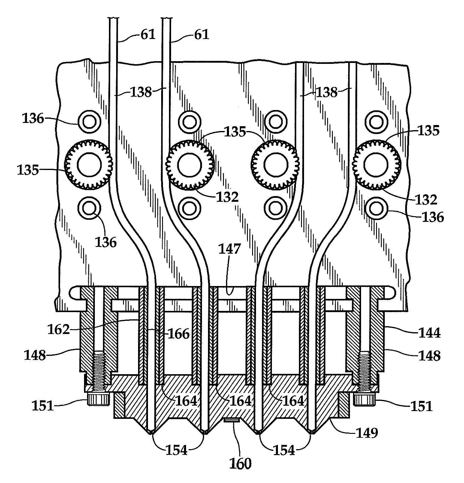
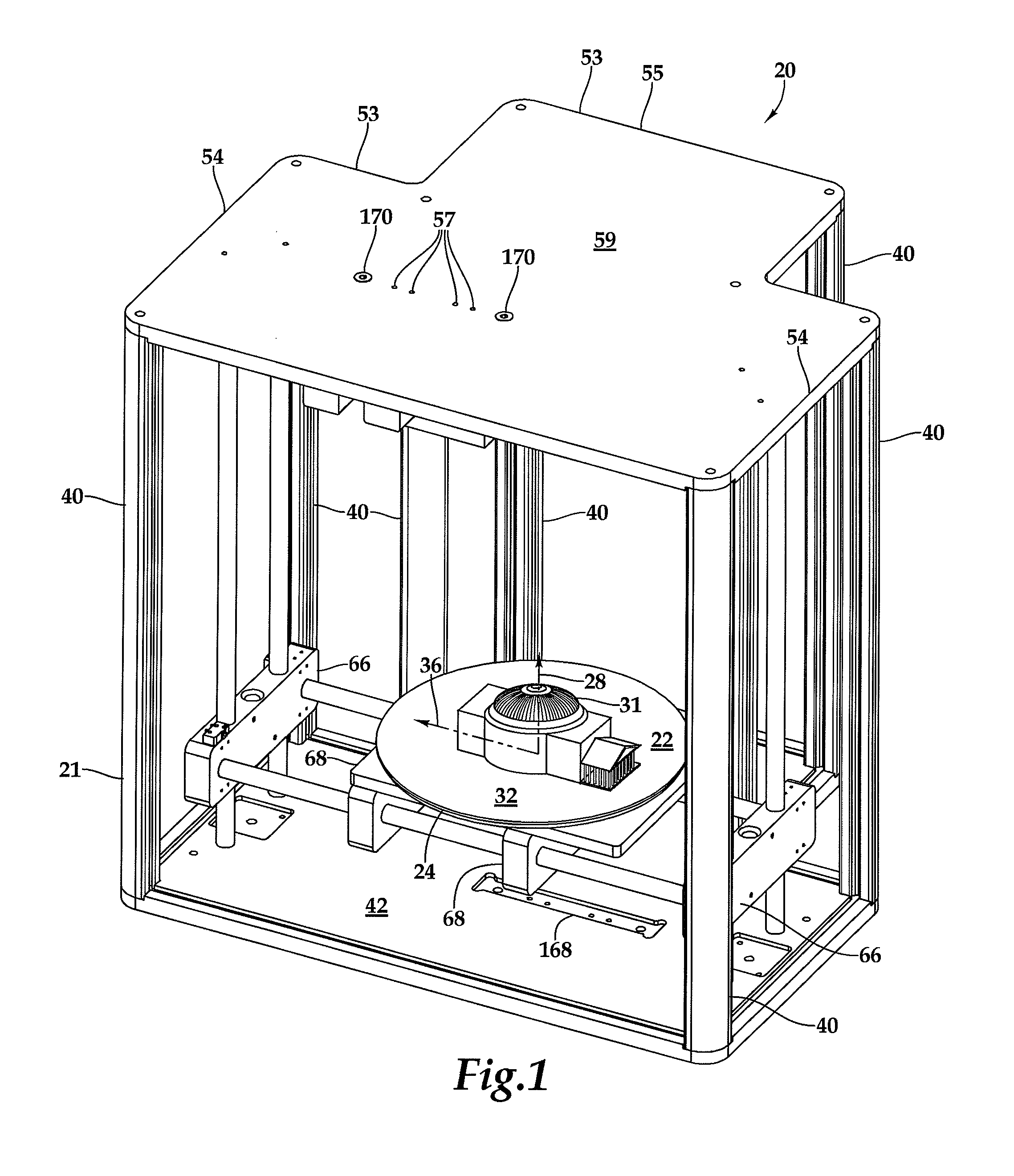
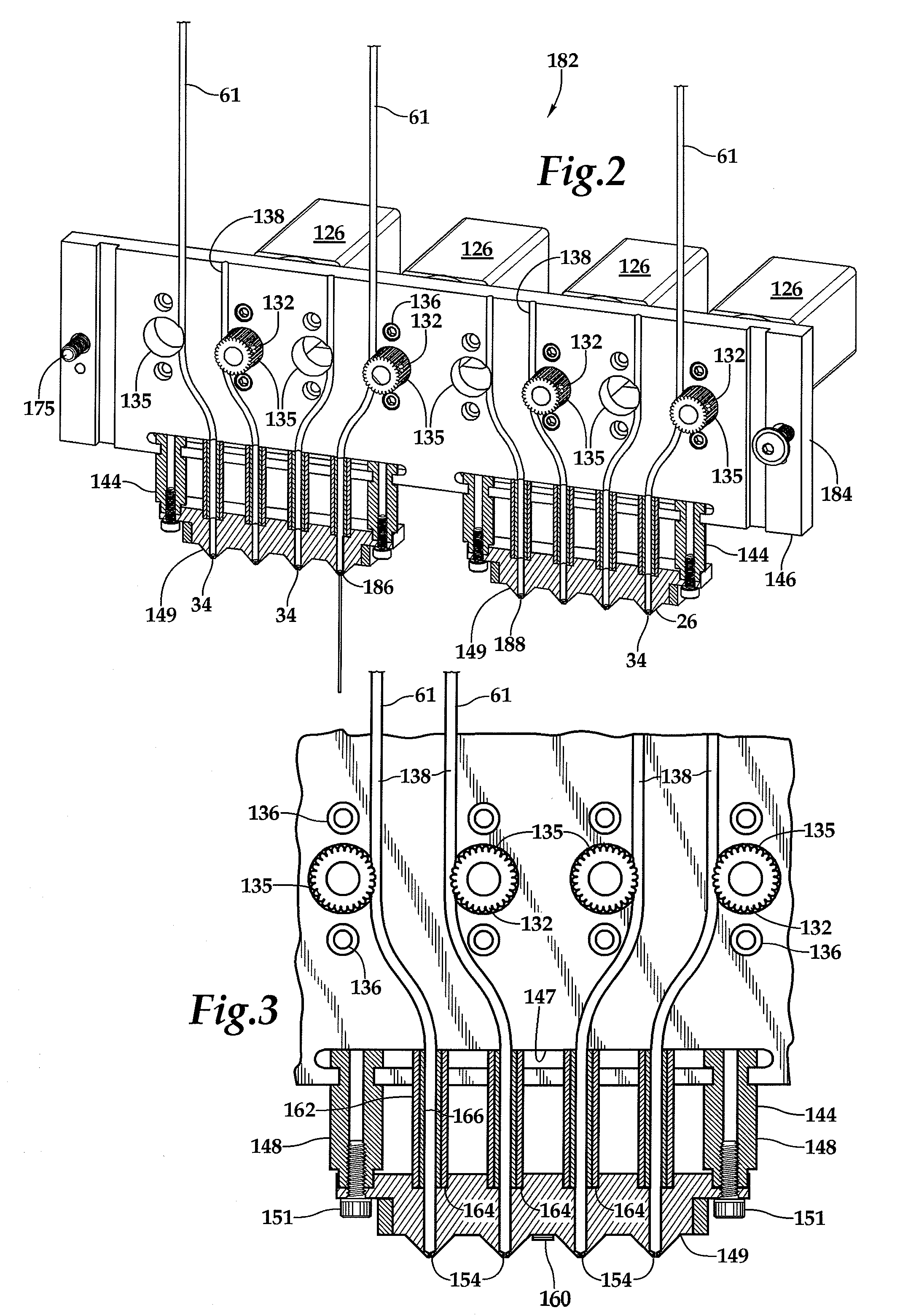
[0020]Referring more particularly to exemplar FIGS. 1-6, wherein like numbers refer to similar parts, a fused filament fabrication stereo lithographic printer 20 is shown in FIG. 1. The printer 20 has a frame 21 which for clarity is shown without lead screws and drive motors (such as shown in U.S. application Ser. No. 13 / 750,731). The printer 20 provides movement of a printer build platform 24 along three degrees of freedom to position various portions 22 of the printer build platform beneath a plurality of fixed printheads 26 as shown in FIG. 2. The printheads 26 have tips 34 through which thermoplastic polymers or metals are extruded. The three degrees of freedom include a first degree of freedom of rotation of the build platform 24 about a z-axis 28 as shown in FIG. 1. The build platform 24 defines a start-print plane or surface 32. A second degree of freedom is provided by linear motion on a cross slide along a radius along a y-axis 36 perpendicular to a z-axis 28. A third degre...


PUM

PropertyMeasurementUnit
thermal conductivityaaaaaaaaaa
melting pointaaaaaaaaaa

Abstract

A fused filament fabrication printer has a fixed extrusion module having multiple printheads having print tips. The fixed arrangement of the printing heads allows the close spacing of multiple print tips in a printhead unit, and the simple routing of multiple plastic or metal filaments to the individual printing heads. The closely spaced print tips in the printhead unit share common components. An exemplary printhead unit has four printing heads which share a common heating block and heating block temperature sensor. The heating block incorporates a group of four print tips evenly spaced along a line. Each printing head has a separate filament which is controlled and driven by its own stepper motor through the heating block to one of the print tips. Printing of a part is by control of individual stepper motors which drive filaments through the heating block and through one of the printing tips.

Description

CROSS REFERENCES TO RELATED APPLICATIONS[0001]The present application is a continuation-in-part of U.S. application Ser. No. 13 / 750,731 filed on Jan. 25, 2013 which is incorporated herein by reference.STATEMENT AS TO RIGHTS TO INVENTIONS MADE UNDER FEDERALLY SPONSORED RESEARCH AND DEVELOPMENT[0002]Not applicable.BACKGROUND OF THE INVENTION[0003]The present invention relates to extrusion-based 3-D printers, termed fused deposition modeling or fused filament fabrication printers, in general and more particularly to printers using a printhead which applies layers of thermoplastic (e.g. ABS, HDPE, PLA, PVA) a metal or metal containing carrier, or polymers and composites that are doped with a variety of secondary materials such as wood and carbon nano-tubes to create models, prototypes, patterns, and production parts.[0004]Fused filament fabrication works on an “additive” principle by laying down material in layers. This technique was initially developed by S. Scott Crump in 1989 and is ...

Claims


Application Information

Patent Timeline
Patent Type & Authority Patents(United States)
IPC IPC(8): B28B1/16
CPCB28B1/16B29C67/0055B29C67/0085B29C64/106B29C64/118B29C64/209
Inventor SCHUMACHER, NATHAN D.PATTERSON, NATHAN J.HARRIS, KEVIN L.BAKKEN, TODD J.
Owner RADIANT FABTION
Why Eureka
Try Eureka