
Three-phase electric-motor winding with differing turn numbers forming fractional effective turns

a technology of three-phase electric motors and windings, applied in the direction of motor/generator/converter stoppers, electric generator control, dynamo-electric converter control, etc., can solve the problems of inability to supply current from the amplifier to the motor, the way the windings are inserted, and the inability to operate the motor. to achieve the effect of solving the problem

Active Publication Date: 2014-09-16
OKUMA CORP
View PDF46 Cites 5 Cited by
  • Summary
  • Abstract
  • Description
  • Claims
  • Application Information

AI Technical Summary

Benefits of technology

The present invention solves a problem where the motor can only generate an output when the number of turns is an integer. The invention provides a solution by allowing a fractional number to be selected for the number of turns, which allows the motor to generate more output. This results in better utilization of the motor's capabilities.

Problems solved by technology

If the voltage generated in the winding reaches a power supply voltage of an amplifier connected to the motor, it becomes impossible to supply current from the amplifier to the motor, and the motor cannot be operated.
However, because the lamination factor is limited within a certain value as described above, there is a problem on how the windings are inserted within the determined lamination factor.
However, in this case, although the motor has a capability to satisfy the specification, the capability of the motor cannot be fully utilized due to limitation that the number of turns must be an integer.

Method used


Image

  • Three-phase electric-motor winding with differing turn numbers forming fractional effective turns
  • Three-phase electric-motor winding with differing turn numbers forming fractional effective turns
  • Three-phase electric-motor winding with differing turn numbers forming fractional effective turns

Examples


Embodiment Construction

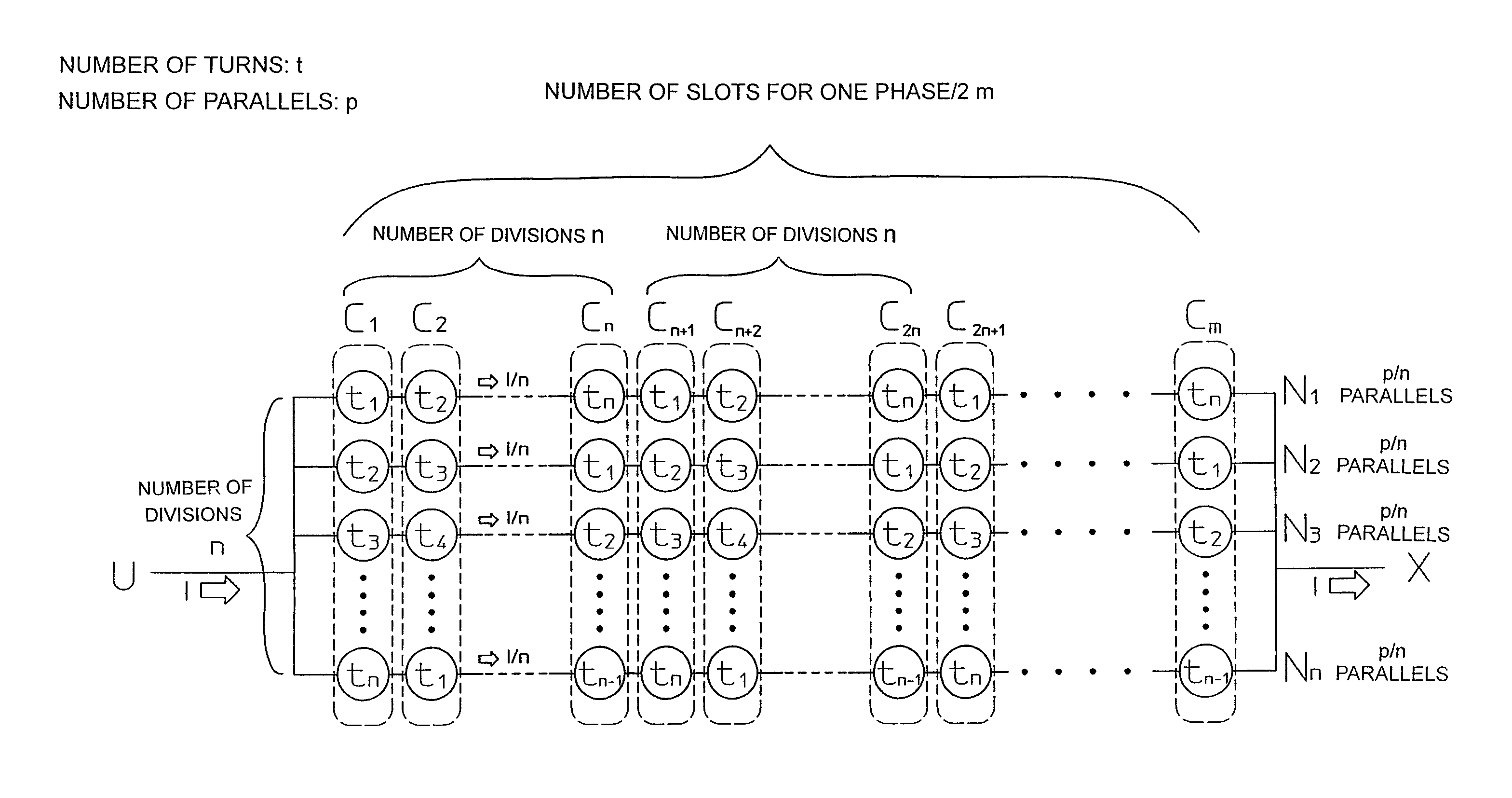
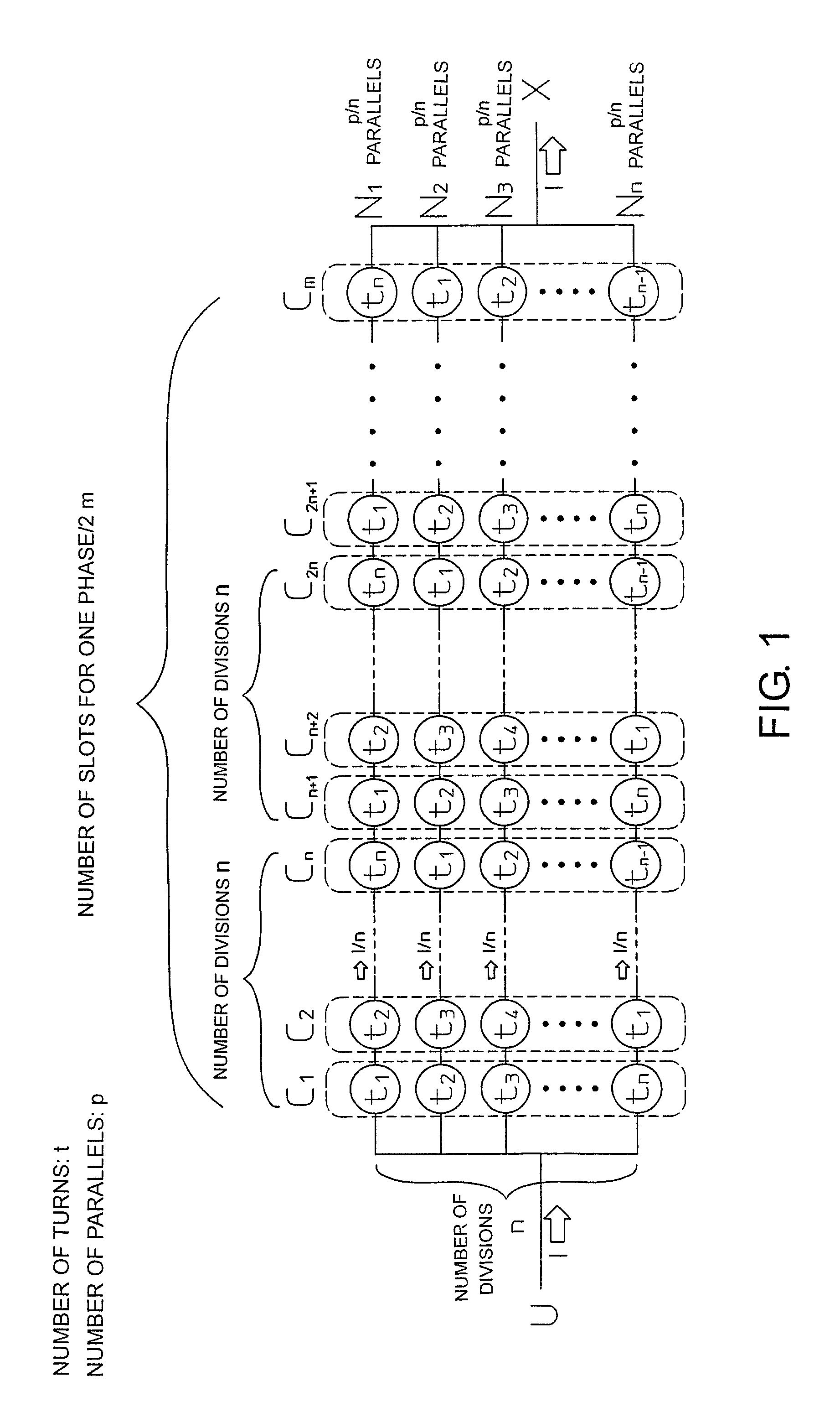
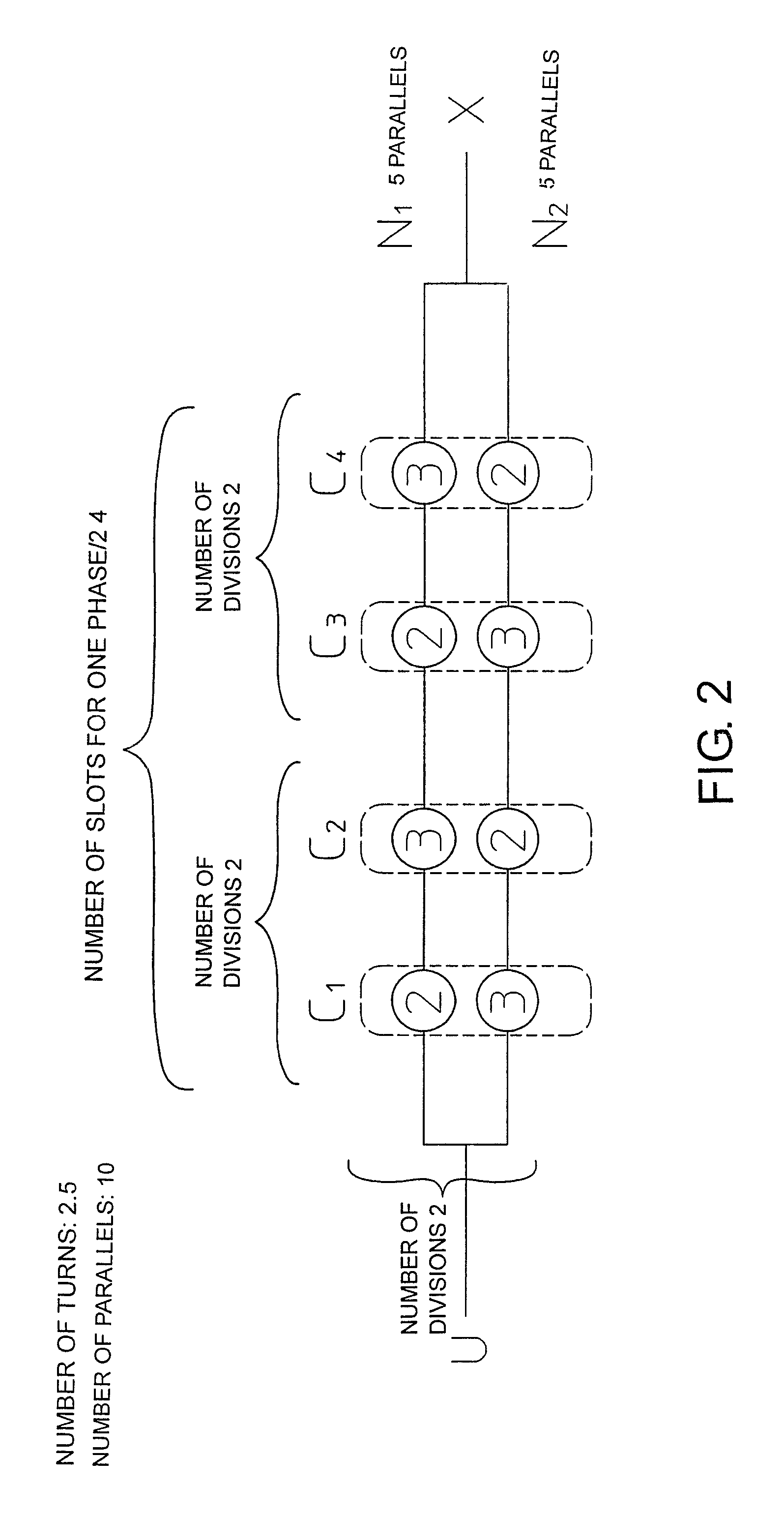
[0022]FIG. 1 is a schematic diagram showing a structure of a winding method of a winding for a motor according to a preferred embodiment of the present invention. In FIG. 1, a winding of one phase is shown between a point shown by U and a point shown by X. FIG. 1 shows a winding of a number of turns t per slot and a number of parallels of p. This group of parallel windings of a total number of parallels p (hereinafter called “overall parallel winding”) is divided into n groups of parallel windings (hereinafter called “partial parallel windings”) as shown by N1, N2, . . . Nn. Each of the divided partial parallel windings N1, N2, . . . Nn comprises an equal number of windings (that is, p / n windings). In other words, all of the partial parallel windings N1, N2, . . . Nn are wound with p / n parallels. Here, p / n is the number of parallels (number of parallels of windings), and, thus, must be an integer. Therefore, n is selected from the divisors of p or p must be selected to be a multiple...


PUM


Abstract

A motor is provided. When m is half of a number of slots of one phase and n is a divisor of m, the overall parallel winding of a total number of parallels p is equally divided n-fold into partial parallel windings Ni, having a number of parallels p / n, each partial parallel winding Ni comprises m sub-coils, the m sub-coils including n types of m / n sub-coils having a number of turns tj, at least one of the sub-coils differing in number of turns from the other sub-coils, and, for each pair of the slots in the stator, one sub-coil of each partial parallel winding Ni is wound around the pair of slots, and n sub-coils wound around the pair of the slots include every one of the n types of the sub-coils of the numbers of tj.

Description

CROSS-REFERENCE TO RELATED APPLICATION[0001]This application claims priority to Japanese Patent Application No. 2010-285616, filed on Dec. 22, 2010, which is incorporated herein by reference in its entirety.BACKGROUND[0002]1. Technical Field[0003]The present invention relates to a motor, and in particular to a winding structure of a winding in a motor.[0004]2. Background Art[0005]A motor comprises a stator and a rotor. Of these, a winding is wound around the stator, and an electric current is applied to the winding to generate a torque and rotate the rotor. The winding wound around the stator is placed in slots within the stator. The number of windings passing inside the slots is normally set such that a certain number of windings are provided in parallel, and are wound through the same slot for a predetermined number of times. The number of lines to be provided in parallel is called a number of parallels, and the number of times the windings are wound in the same slot for a plurali...

Claims


Application Information

Patent Timeline
Patent Type & Authority Patents(United States)
IPC IPC(8): H02K3/28H02K3/12
CPCH02K3/28
Inventor YOKOCHI, TAKANORI
Owner OKUMA CORP
Learn More