High energy proton or neutron source

a proton or neutron source, high-energy technology, applied in the direction of direct voltage accelerators, accelerators, chemical to radiation conversion, etc., can solve the problems of high-energy radiation that requires special shielding facilities, large amount of high-energy radiation, and high cost of shielding facilities

Active Publication Date: 2014-09-16
SHINE TECH LLC
View PDF34 Cites 25 Cited by
  • Summary
  • Abstract
  • Description
  • Claims
  • Application Information

AI Technical Summary

Benefits of technology

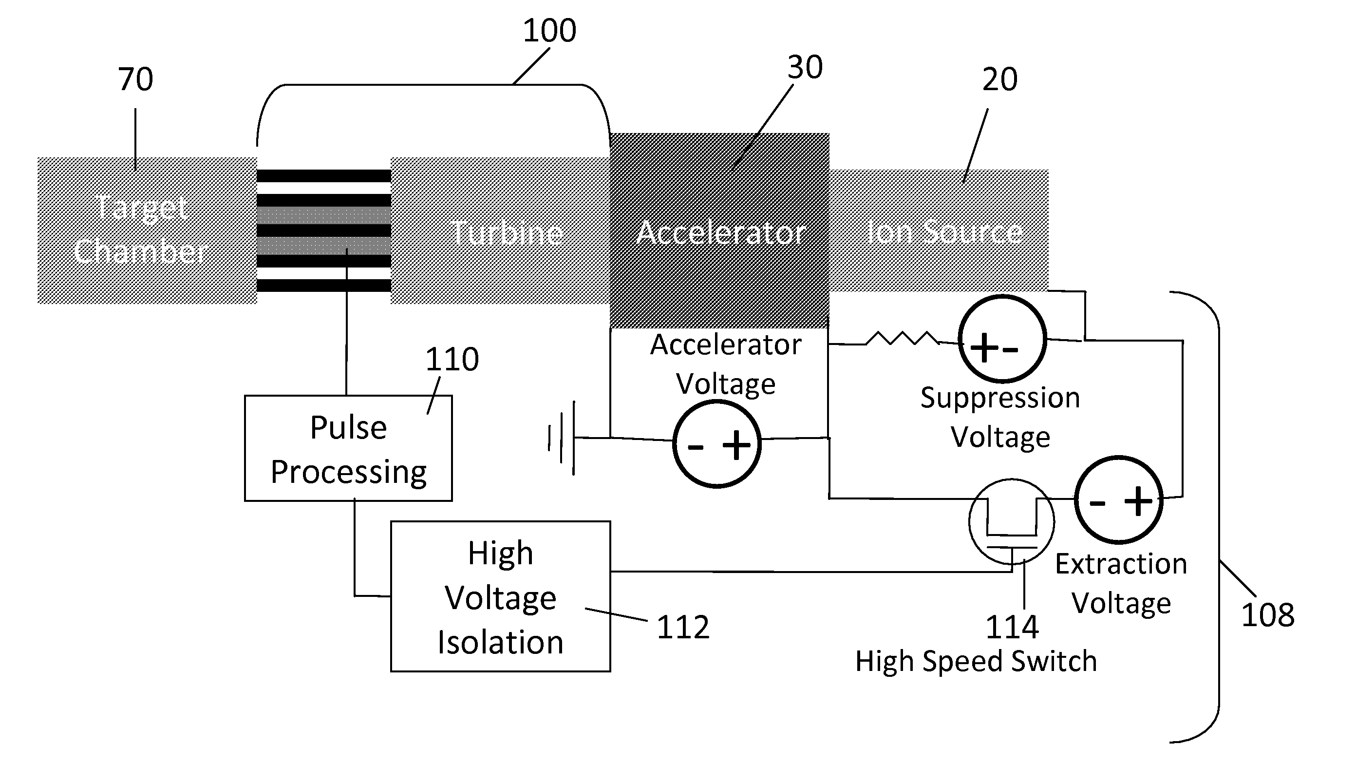
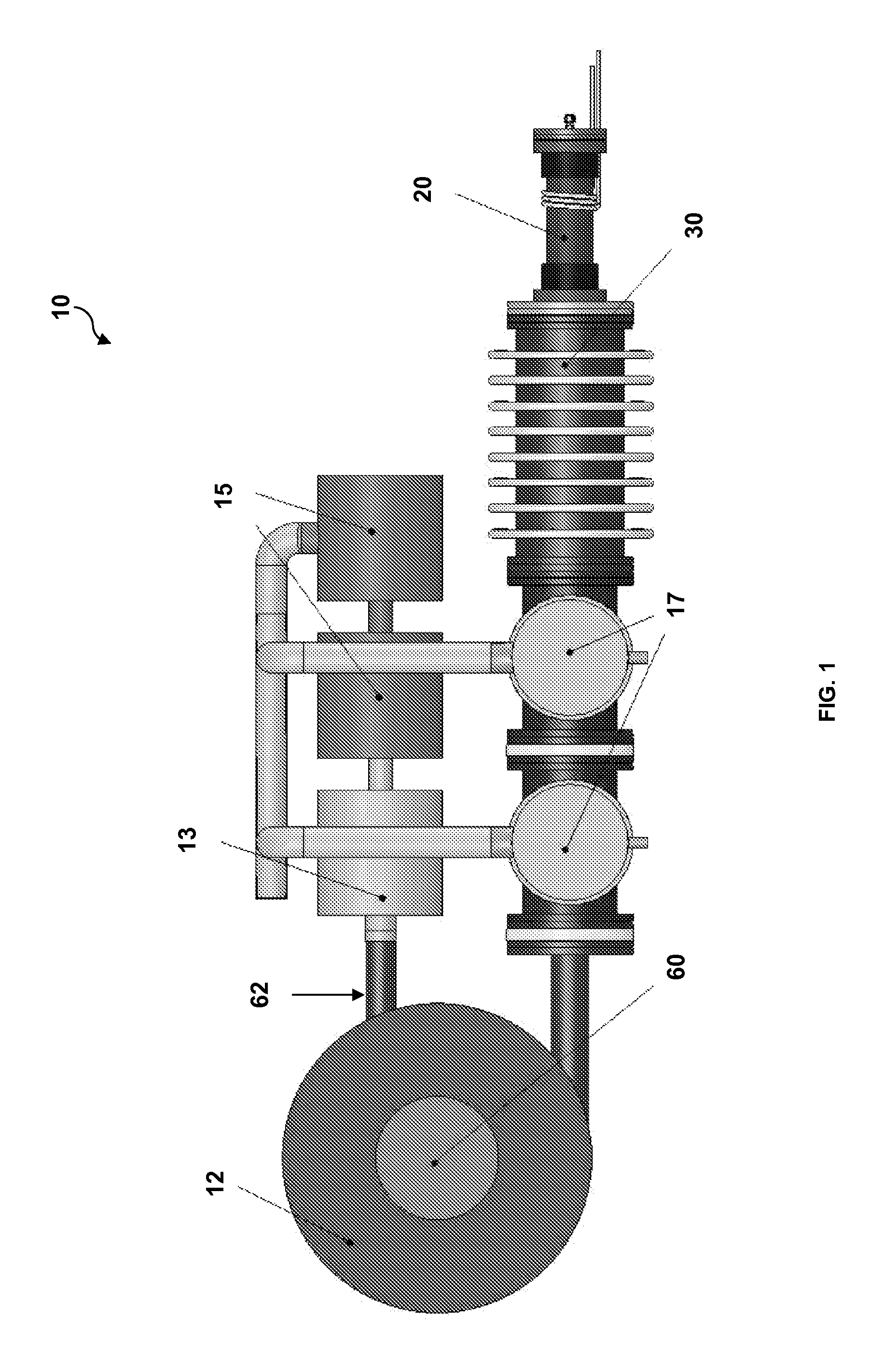
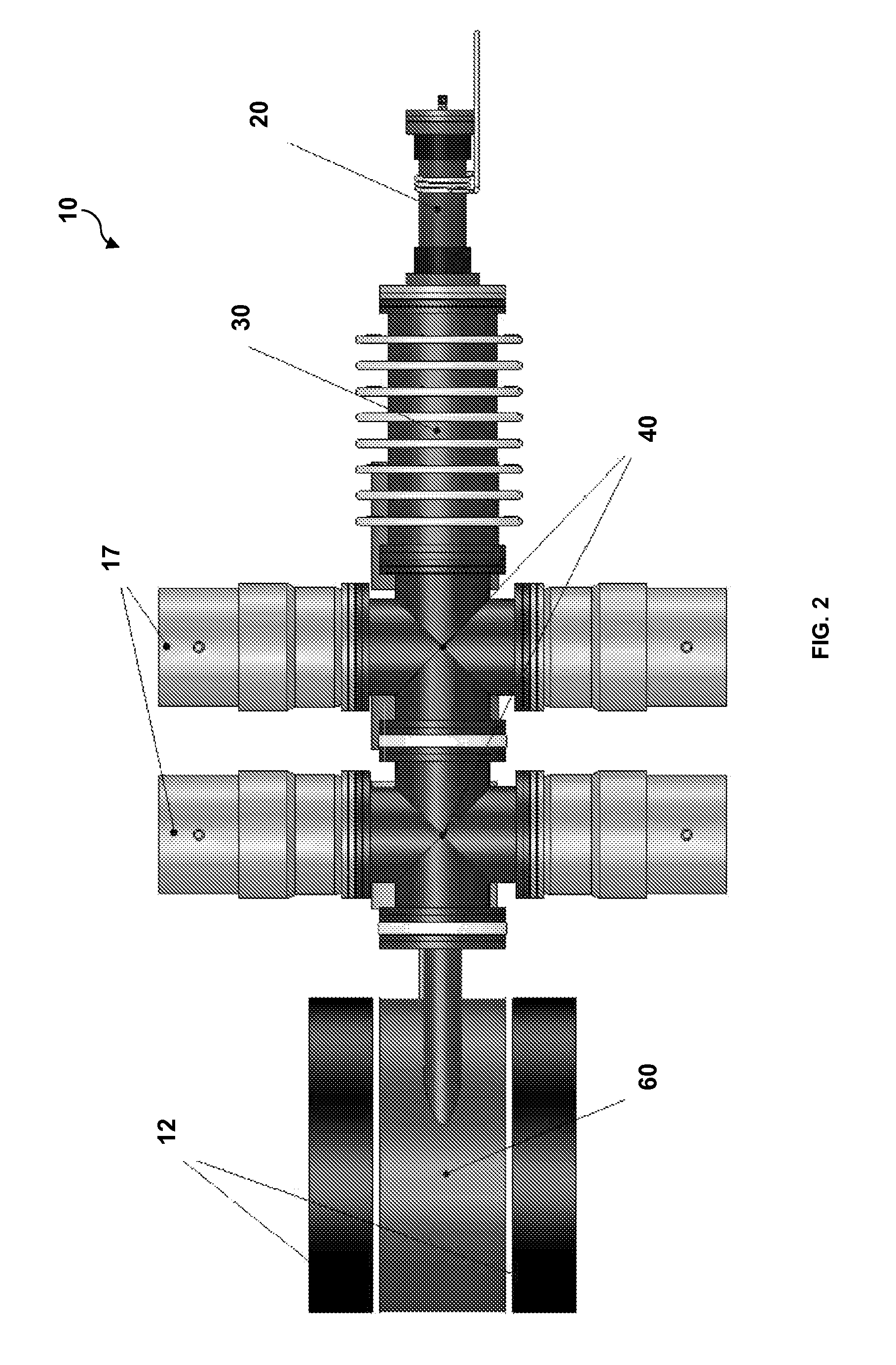
[0006]A high energy compact proton or neutron source embodying the principles of the invention overcomes the disadvantages of prior proton or neutron sources. The device in accordance with the invention may generate either protons or neutrons by changing the fuel type and acceleration voltage. The device includes an ion source, an accelerator, and a target system which is dimensioned and configured as a magnetic target chamber, a linear target chamber operationally coupled to a high speed synchronized pump, or a linear target chamber and an isotope extraction system. The high energy proton source in accordance with the invention may further include a high-speed pump that is synchronized with the ion source flow from the accelerator. This synchronized high speed pump prevents most material from escaping the target chamber and may obviate the need for a differential pumping system and / or allow for a smaller linear target chamber to be used.
[0007]In one aspect, the invention provides a high energy, low radiation proton source for the generation of medical isotopes. The source, in accordance with the invention, produces high energy protons (>10 MeV) through 2H—3He fusion reactions. The generated isotopes may be used in positron emission tomography (PET) diagnostic procedures as well as other imaging and treatment procedures. Specifically, the proton source in accordance with the invention may be used to generate isotopes such as 18F, 11C, 15O, 124I, and 13N. The ability to create 13N, 11C, and 15O in a low radiation device in accordance with the invention may further facilitate the development of new imaging procedures.
[0008]In another aspect, the invention provides a high energy proton source for medical isotope generation in a device that is less expensive and more compact than conventional technologies such as cyclotrons. The high energy proton source for medical isotope generation produces minimal radiation compared to conventional technologies, minimizing or eliminating the need for special bunkers to house the generator, and thus allowing for the greater access for patients.
[0009]In yet another aspect, the invention provides a high energy proton source for medical isotope generation that can operate with a combination of high target chamber pressure and low accelerator section pressure by utilizing a specialized differential pumping system. This combination allows for high operational voltages (300 kV to 500 kV or more) while producing high output yields (>1013 protons / sec) of high energy protons (>10 MeV). The invention may incorporate a magnetic target chamber that permits operation at lower target chamber pressures and with a smaller target chamber than conventional beam-target accelerator devices. In the magnetic target chamber, fuel ions circle the magnetic field lines, yielding a long path length in a short chamber compared to a beam that would pass in a nearly straight line through a longer chamber.

Problems solved by technology

These conventional sources have many disadvantages including being massive and costly structures, and producing a substantial amount of high-energy radiation that requires special shielding facilities.
Shielded facilities are generally expensive and available in only a few locations.
Additionally, sources, such as cyclotrons and linacs, have the disadvantage of a limited target lifetime when used as a neutron source.
Few of these source facilities are located at health care facilities, making it difficult to treat patients who may benefit from use of isotopes, especially isotopes with short half-lives due to the rapid decay.
In addition to limited access, existing devices suffer from various technical problems, depending on the type of device.
For solid target-based devices, the target may be damaged quickly by helium irradiation as in the case where the beam is comprised of helium particles, or the target quickly becomes loaded with deuterium as when the beam is comprised of deuterium particles.
Such deuterium loading removes helium from the target (decreasing the yield quickly in time) and is a source of unwanted 2H—2H nuclear reactions, which create high energy neutrons and necessitate significant shielding.
Furthermore, the number of protons that can be captured usefully in a solid target device may be limited because the protons are emitted isotropically and many will be buried deeper into the target material.
In addition to short target lifetime, output of these devices may be limited due to challenges associated with keeping the target cool.
For existing gas target-based devices, limitations may include an ion beam that fails to reach full energy needed for reaction such as in IEC (inertial electrostatic confinement) devices in beam-background mode, or short lifetime of a thin window separating a high pressure target and low pressure accelerator region.
Too high or too low a pressure can cause inefficient operation, and resulting output levels may be too low to be useful for applications including medical procedures.
These and other limitations of conventional proton or neutron sources prevent isotope generation from being available to small or remote communities, and additionally require substantial capital investments for such large facilities.

Method used


Image

  • High energy proton or neutron source
  • High energy proton or neutron source
  • High energy proton or neutron source

Examples


example 1

Neutron Source with Magnetic Target Chamber

[0083]Initially, the system will be clean and empty, containing a vacuum of 10−9 torr or lower, and the high speed pumps will be up to speed (two stages with each stage being a turbomolecular pump). Approximately 25-30 standard cubic centimeters of gas (deuterium for producing neutrons) will be flowed into the target chamber to create the target gas. Once the target gas has been established, that is, once the specified volume of gas has been flowed into the system and the pressure in the target chamber reaches approximately 0.5 torr, a valve will be opened which allows a flow of 0.5 to 1 sccm (standard cubic centimeters per minute) of deuterium from the target chamber into the ion source. This gas will re-circulate rapidly through the system, producing approximately the following pressures: in the ion source the pressure will be a few mtorr; in the accelerator the pressure will be around 20 μtorr; over the pumping stage nearest the accelera...

example 2

Neutron Source with Linear Target Chamber

[0086]Initially, the system will be clean and empty, containing a vacuum of 10-9 torr or lower and the high speed pumps will be up to speed (three stages, with the two nearest that accelerator being turbomolecular pumps and the third being a different pump such as a roots blower). Approximately 1000 standard cubic centimeters of deuterium gas will be flowed into the target chamber to create the target gas. Once the target gas has been established, a valve will be opened which allows a flow of 0.5 to 1 sccm (standard cubic centimeters per minute) from the target chamber into the ion source. This gas will re-circulate rapidly through the system, producing approximately the following pressures: in the ion source the pressure will be a few mtorr; in the accelerator the pressure will be around 20 μtorr; over the pumping stage nearest the accelerator, the pressure will be <20 μtorr; over the center pumping stage the pressure will be ˜50 mtorr; over...

example 3

Proton Source with Magnetic Target Chamber

[0090]Initially, the system will be clean and empty, containing a vacuum of 10−9 torr or lower, and the high speed pumps will be up to speed (two stages with each stage being a turbomolecular pump). Approximately 25-30 standard cubic centimeters of gas (an approximate 50 / 50 mixture of deuterium and helium-3 to generate protons) will be flowed into the target chamber to create the target gas. Once the target gas has been established, that is, once the specified volume of gas has been flowed into the system and the pressure in the target chamber reaches approximately 0.5 torr, a valve will be opened which allows a flow of 0.5 to 1 sccm (standard cubic centimeters per minute) of deuterium from the target chamber into the ion source. This gas will re-circulate rapidly through the system, producing approximately the following pressures: in the ion source the pressure will be a few mtorr; in the accelerator the pressure will be around 20 μtorr; ov...


PUM


Abstract

The invention provides a compact high energy proton source useful for medical isotope production and for other applications including transmutation of nuclear waste. The invention further provides a device that can be used to generate high fluxes of isotropic neutrons by changing fuel types. The invention further provides an apparatus for the generation of isotopes including but not limited to 18F, 11C, 15O, 63Zn, 124I, 133Xe, 111In, 125I, 131I, 99Mo, and 13N.

Description

CROSS-REFERENCE TO RELATED APPLICATIONS[0001]This application is the U.S. national stage filing of International Application No. PCT / US2008 / 088485, filed Dec. 29, 2008, which is incorporated herein by reference in its entirety and claims priority to U.S. Provisional Patent Application No. 61 / 017,288, filed Dec. 28, 2007, and U.S. Provisional Patent Application No. 61 / 139,985, filed Dec. 22, 2008, which are incorporated herein by reference in their entireties.INTRODUCTION[0002]Proton and neutron sources, such as nuclear reactors, spallation devices, cyclotrons, linacs, or existing beam-target accelerator devices, are typically used to produce short-lived radioisotopes for medical applications. These conventional sources have many disadvantages including being massive and costly structures, and producing a substantial amount of high-energy radiation that requires special shielding facilities. Shielded facilities are generally expensive and available in only a few locations. Additional...

Claims


Application Information

Patent Timeline
Patent Type & Authority Patents(United States)
IPC IPC(8): G21G1/10H05H6/00
CPCG21G1/10H05H6/00
Inventor PIEFER, GREGORY
Owner SHINE TECH LLC
Why Eureka
Try Eureka