Spring clip

a technology of solar panels and support structures, applied in the direction of solar thermal energy generation, solar heating energy, ceilings, etc., can solve the problems of high installation costs, labor-intensive installation, and poor mechanical properties, and achieve the effects of avoiding sagging, facilitating superior support of panels, and reducing standing water accumulation

Active Publication Date: 2014-09-23
NORTHERN STATES METALS
View PDF238 Cites 71 Cited by
  • Summary
  • Abstract
  • Description
  • Claims
  • Application Information

AI Technical Summary

Benefits of technology

[0022]It is another object of the present invention to provide a support and installation system for solar panels in which the panels are less likely to be damaged during installation.
[0054]It is the overall goal of the present invention to provide a comprehensive panel mounting system that facilitates rapid and secure installation, including deployment of the panel support structure, and placement of the panels on that support structure.

Problems solved by technology

Typically, these support systems are costly, heavy, structurally inferior, mechanically complicated and the installation is labor-intensive.
Once the support structure is in place, mounting the solar panels on the support structure can be very difficult.
It is further complicated by the tendency of some large solar panels to sag and flex, thereby rendering the panel mounting unstable.
Panel repair and adjustment thereby become more difficult.
This installation process, especially if involving multiple clips 45, is often costly, inaccurate, dangerous and time-consuming.
However, even with a reliable, easily-deployed support array, there are still difficulties in the installation of the panels themselves, especially solar panel arrays.
In particular, existing support systems require meticulous on-site assembly of multiple parts, performed by expensive, dedicated field labor.
Assembly is often performed in unfavorable working conditions, i.e. in harsh weather or in difficult terrain, without the benefits of quality control safeguards and precision tooling.
This can jeopardize the supported solar panels.
Another problem is the spacing of the photovoltaic (solar) panels 12.
It is also challenging to precisely space the panels on-site using existing support structures and panel clips 45, without advanced (and expensive) technical assistance.
Unfortunately, the operation of drilling the holes on-site requires skilled workers, and even with skilled installation, misalignment of the support structure and / or the solar panels supported by the structure may still occur (i.e. improperly spaced or slightly skewed from parallel).
If this process is executed on-site, accurate placement of the solar panels becomes extremely difficult.
This is an awkward arrangement, even in the hands of expert installers.
Despite the effectiveness of this particular arrangement, there are still difficulties to be addressed, as elaborated on below.
Misalignment difficulties are exacerbated by the flexing of the panels 12 and sagging permitted by the natural flexibility of the panels.
Improper installation, which occurs frequently in conventional systems, can lead to dislocation of the panels due to sagging or atmospheric conditions.
The use of a wide variety of different mounting positions and panel array arrangements also worsens the stability problems caused by panel sagging or deflection.
Further, certain mounting positions will make the panels 12 more vulnerable to atmospheric disruptions, such as those created by wind and precipitation.
All of these variables also complicate electrical connections to the panels.
However, there are drawbacks in this approach.
In particular, there are only a limited number of points at which panel clips can be connected.
The problems caused by misalignment due to sagging are further exacerbated in some environments by the accumulation of ice on the panels.
Icing can also be a problem, particularly when water works its way into crevasses found throughout the overall panel array 10, and then freezes and expands.
Still further, icing can become particularly problematic with respect to panel clips 45 extending beyond the panels 12 or the support rails 30.
This in turn necessitates adjustments in the panel holding structures, which are often not successful since they are conventionally limited to two edges of the panel.
At present, none of the conventional panel support systems offer the capabilities of eliminating the problems mentioned above.

Method used


Image

  • Spring clip
  • Spring clip
  • Spring clip

Examples


Embodiment Construction

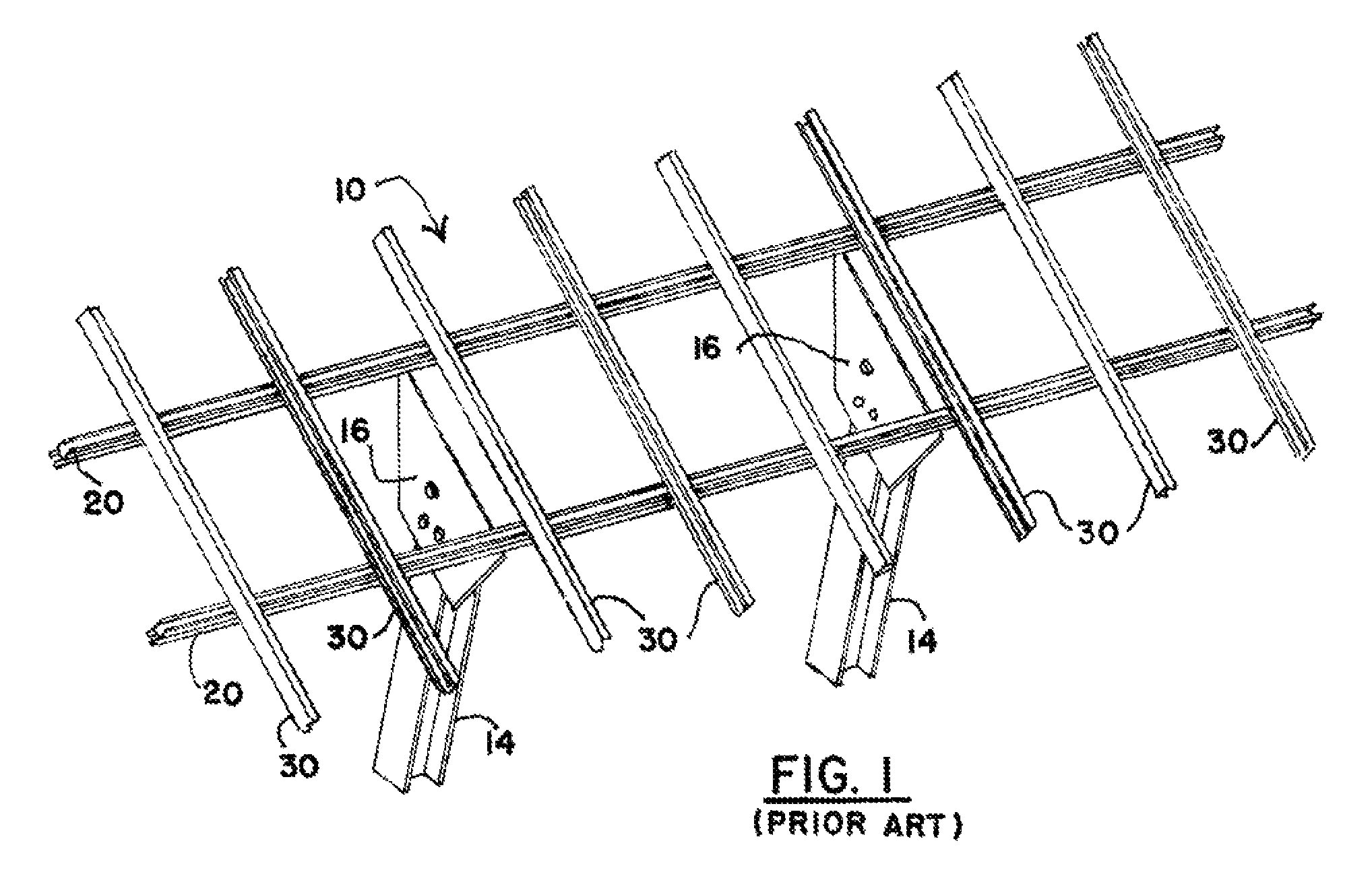
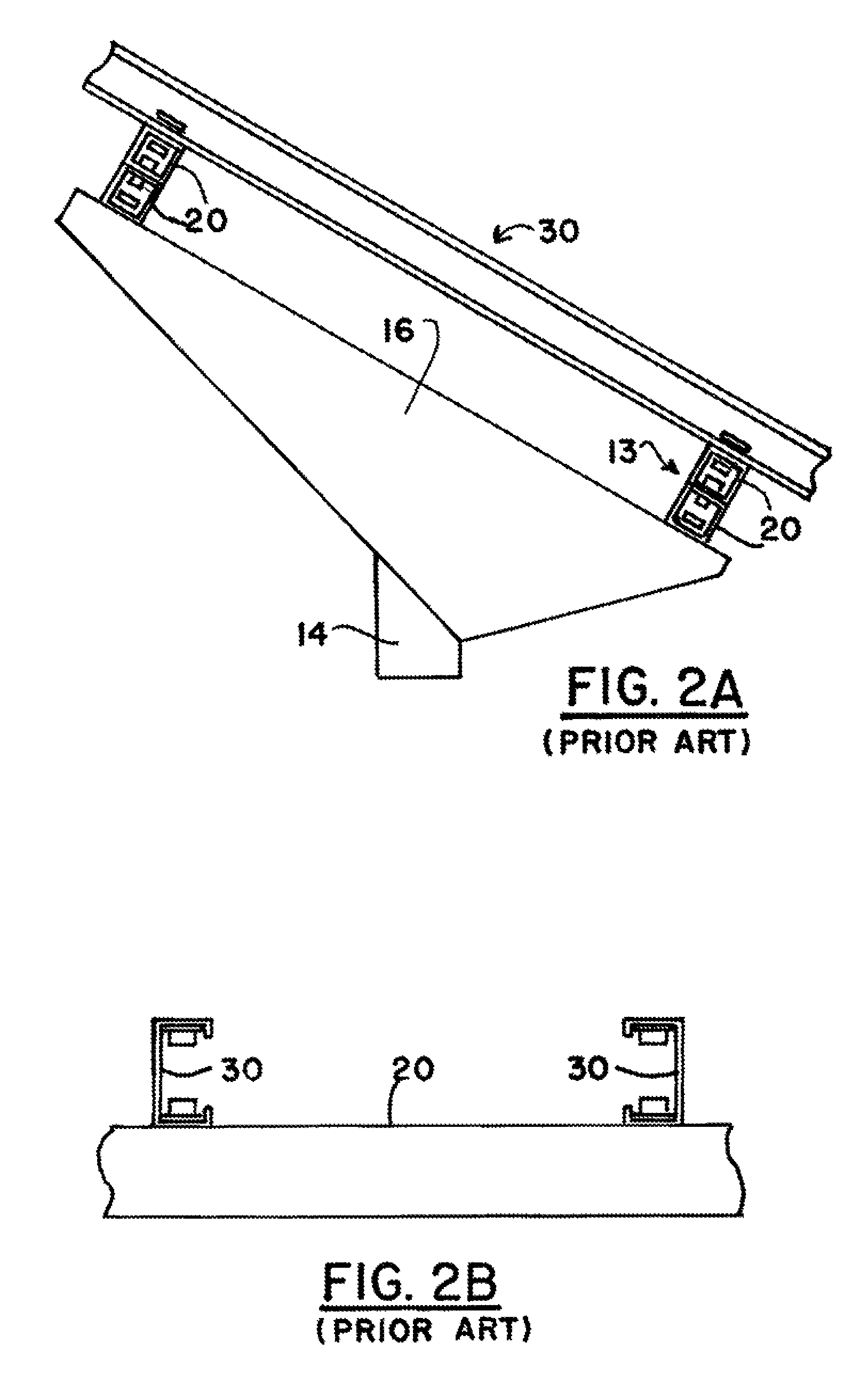
[0078]As has been previously discussed, conventional panel (solar and other types) support systems tend to be constituted by two dimensional arrays having lower support joists 20 and upper support rails 30. Panel clips or holders 45 are then field-mounted on the upper support rails so that the panels 12 can be placed thereon, and secured with additional portions of the clips. Even with factory pre-alignment and set up of support joists 20 and upper panel rails 30, conventionally, there is little that can be done about the many assembly steps required to place both the panel clips 45 and the panels 12 on the upper support rails 30.

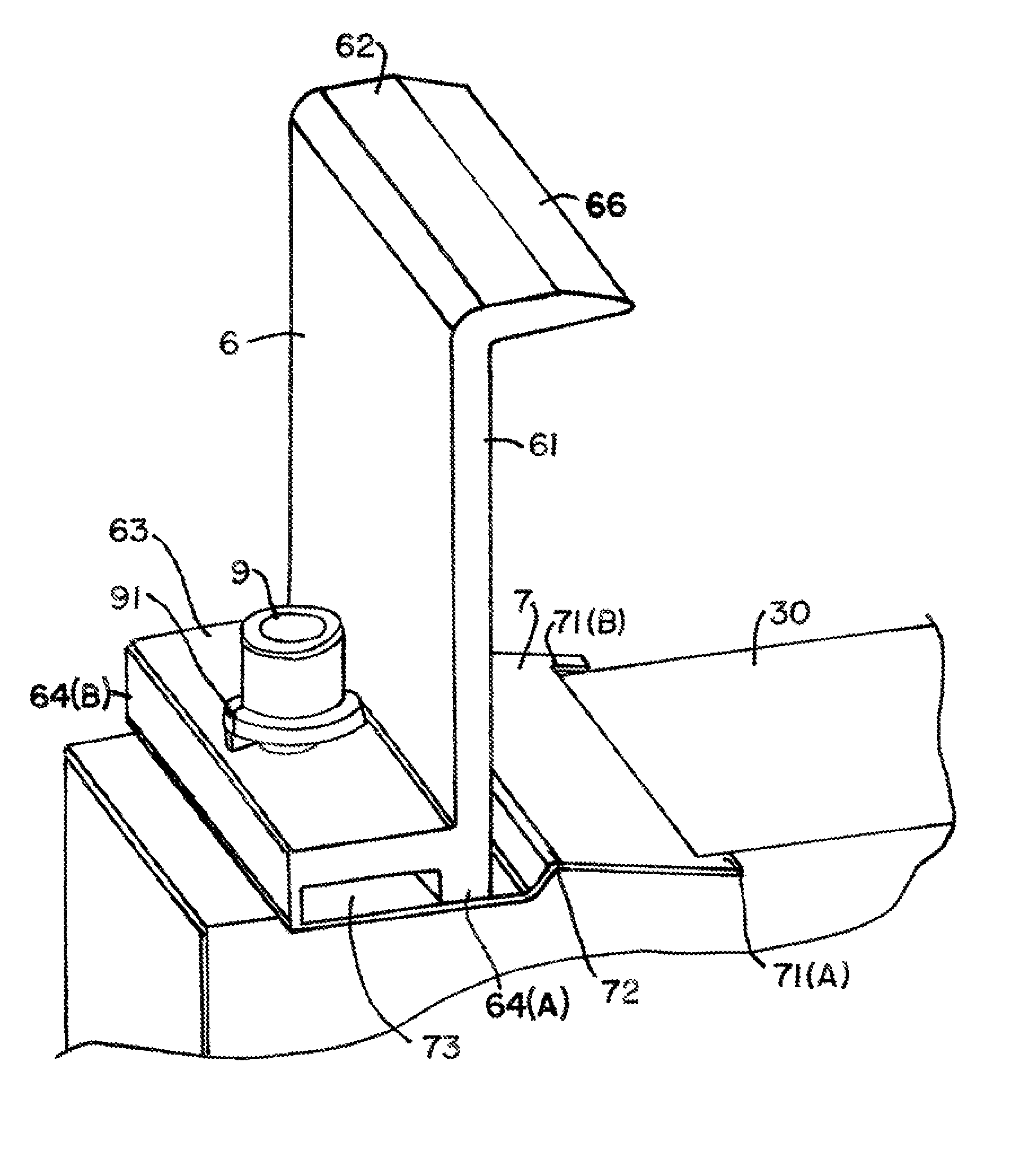
[0079]The present inventions, as depicted in FIGS. 6-18, constitute a departure from the prior arrangements. In particular, panel clips 6 still hold panels 12 along their edges. However, panel rails 30 are not found along the longitudinal (parallel to the length of the panel rails) edges of the panels 12. Rather, the panel rails 30 support panels 12 at posi...


PUM


Abstract

A panel array support assembly has lower support joists supporting varied panel rails, to which are connected panel holding device or clips. The panel clips are spring-based and configured so that the length of each clip extends in a direction along the length of the panel rails. The panels are supported well inside of the edges extending in the same direction as the panel rails.

Description

PRIORITY INFORMATION[0001]This application claims priority to U.S. Provisional Application No. 61 / 441,830, filed on Feb. 11, 2011. The entire subject matter of the provisional application is incorporated herein by reference.FIELD OF THE INVENTION[0002]This invention relates to support systems for panels and panel-like structures, such as solar energy collection systems, and more particularly to a support system for an array of photovoltaic panels, in addition to a method of quickly assembling the same for activation.BACKGROUND OF THE INVENTION[0003]Many conventional photovoltaic (solar) panel arrays include a plurality of solar panels, optimally arranged for converting light incident upon the panels to electricity. Various support systems are used for attachment to roofs, free-field ground racks, tracking units, or other substrates / structures. Typically, these support systems are costly, heavy, structurally inferior, mechanically complicated and the installation is labor-intensive. ...

Claims


Application Information

Patent Timeline
Patent Type & Authority Patents(United States)
IPC IPC(8): E04D13/18E04H14/00F16B5/06F24J2/52H01L31/042H01L31/048
CPCF24J2/5232H01L31/0422H01L31/0482F24J2/5258Y02E10/47Y02E10/50F16B5/0635Y02B10/12H02S20/23H02S20/00Y02B10/20F24S25/12F24S25/636H02S20/10H02S20/30Y02B10/10
Inventor CUSSON, PAUL R.GREENAMYER, MICHAEL G.NOBILE, JOSEPH A.KILAR, JR., THOMAS P.
Owner NORTHERN STATES METALS
Why Eureka
Try Eureka