
System for preventing friendly fire accidents

a technology for preventing fire accidents and preventing fire accidents, applied in the direction of fire alarms, fire alarm radiation actuation, instruments, etc., can solve the problems of unresolved or impractical systems, other systems designed for sport and hunting are not simple and practical, and cannot offer a simple and practical system. , to achieve the effect of preventing friendly fire accidents, facilitating location, and facilitating the location or presence of peopl

Active Publication Date: 2014-09-23
HUNTER SAFETY LAB
View PDF15 Cites 7 Cited by
  • Summary
  • Abstract
  • Description
  • Claims
  • Application Information

AI Technical Summary

Benefits of technology

[0011]It is an advantage of the present invention that it can detect the presence of several passive retro-reflectors located at any range within the predetermined direction.
[0012]It is a further advantage that the present invention does not rely on movement or agitation; for example, the present invention does not rely on being swept back and forth in order to determine peak signal strength, does not require rotation about a vertical axis, nor does it rely on signal modulation from the target to aid detection.
[0013]A significant amount of the prior art describes systems used to facilitate the location or presence of people and property for various purposes, including preventing friendly fire accidents. Many of these systems require the use of a transmitter or transponder to facilitate location. For example: US patent 2011063102 Interrogator-transponder RF system for prevention of hunting accidents; WO2010006484 Direction finding antenna systems and methods of use thereof; U.S. Pat. No. 5,771,002 Tracking system using radio frequency signals; U.S. Pat. No. 5,307,053 Device and method for alerting hunters; U.S. Pat. No. 5,183,951 Weaponry signal apparatus; US patent 2007241913 Hunter proximity detection system; US patent 2011068980 Direction finding method and device; US patent 2010309058 System and methods for direction finding using a handheld device; EP 2278351 Assisted direction finding apparatus; and FR2790547 Hunting accidents firearm activation prevention system having all direction fixed frequency transmitter and firearm attached directional receiver transmitter frequency tuned / activating inhibition mechanism.
[0014]For use in a hunting or tactical situation, the prior art has many limitations:
[0015]a person seeking to be detectable must carry or wear a battery powered transmitter or transponder, thus when the batteries fail, so does their detectability
[0016]light and high frequency radio waves will not travel through the human body so multiple transmitters or transponders must be attached to the body to provide 360 degree coverage

Problems solved by technology

Such systems are relatively complex.
Other systems designed for sport and hunting are unresolved or impractical.
None of these however offer a simple and practical system, suitable for a variety of situations: for example, a system comprising passive retro-reflectors in preference to prior art encoded transmission signals, matched ID codes or powered transponders and transmitters that are paired.
For use in a hunting or tactical situation, the prior art has many limitations:a person seeking to be detectable must carry or wear a battery powered transmitter or transponder, thus when the batteries fail, so does their detectabilitylight and high frequency radio waves will not travel through the human body so multiple transmitters or transponders must be attached to the body to provide 360 degree coveragethe systems using radio frequency at low enough frequency to pass through the user's body are non-directional and are based on proximity sensing, which might yield false positive results from targets not in the direction of interest;it is unclear how interference from one's own radio transmitter or that of a proximal companion can be avoided without the reliance on paired IDs, the use of which would greatly reduce system practicality.
Some of the IFF systems found in the prior art use the properties of retro-reflection to facilitate detection but rely on relatively complex methods of encryption or signal modulation to ensure the response comes from a friend not a foe.

Method used


Image

  • System for preventing friendly fire accidents
  • System for preventing friendly fire accidents
  • System for preventing friendly fire accidents

Examples


example 1

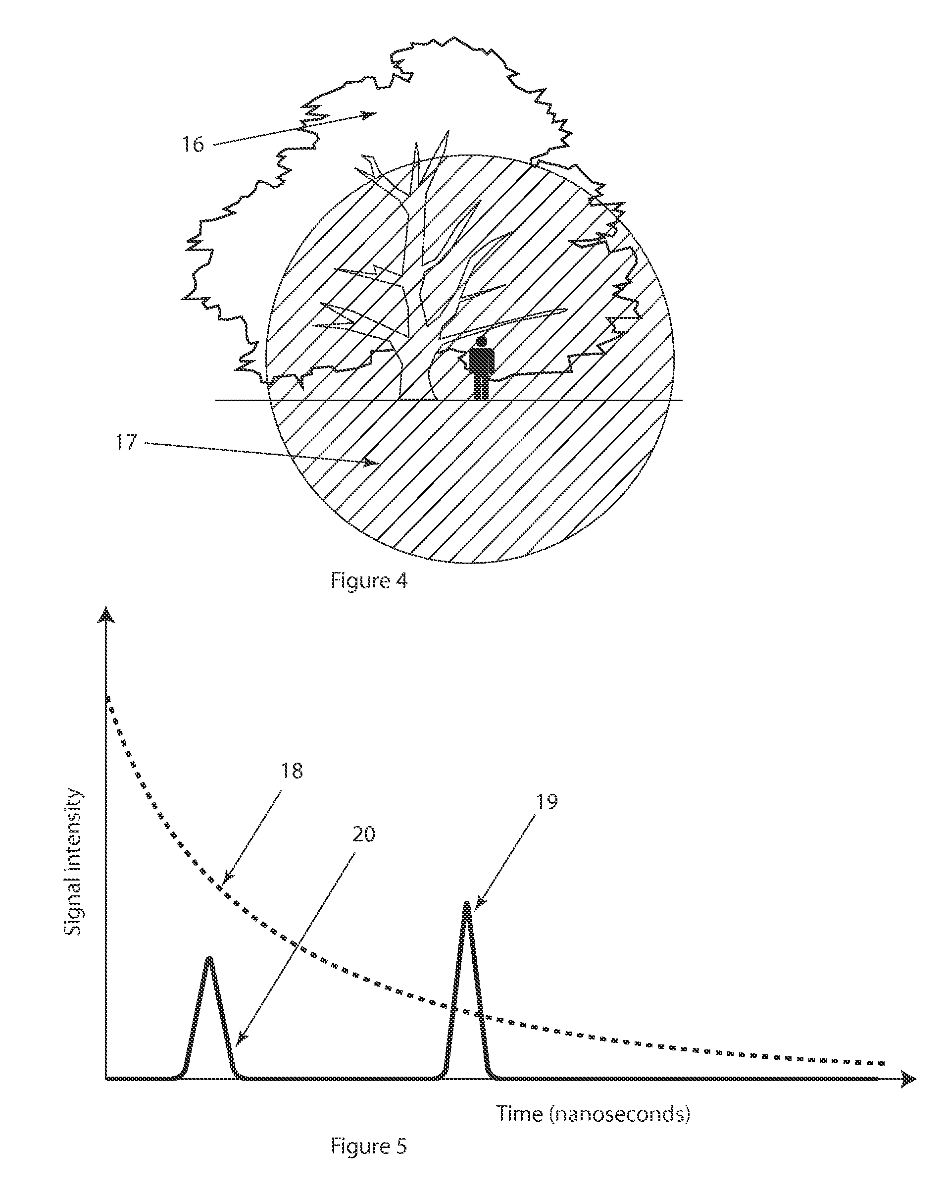
Received Power Due to Reflection from the Background

Assumptions:

[0098]The background is bigger than the beam at any distance, ie all the transmitted power hits the background and atmospheric loss is zero. And reflected power is then output power multiplied by the reflection coefficient. In the worst case the background is very reflective, with a reflection coefficient of 0.8 (eg snow).

Background_Received_Power (W)=[(Pi*Receiver_Aperture_Diameter^2) / 4 / (2*Pi*Range^2)]*(Power_Landing_on_Target)*Target_Reflectivity  Equation A:

Received Power Due to Reflection from Retroreflective Patch:

Assumptions:

[0099]The received power is calculated assuming that no power is reflected from a close by background (this would add significant power to the returned pulse since most of the transmit power misses the small patch). This would be the case if say a hunter was on a ridge above the shooter; the background would likely be empty sky.

[0100]If the patch is larger than the beam (eg at close range) the...


PUM


Abstract

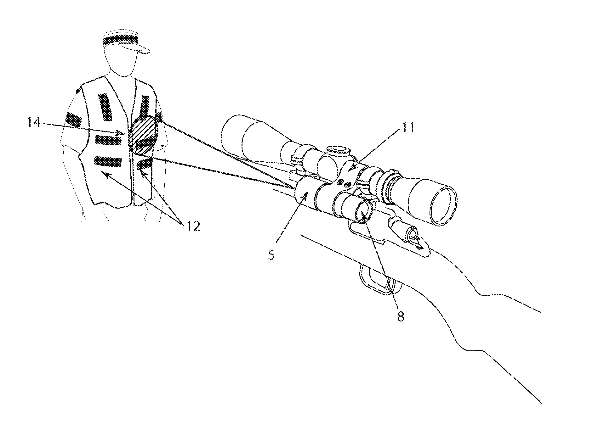
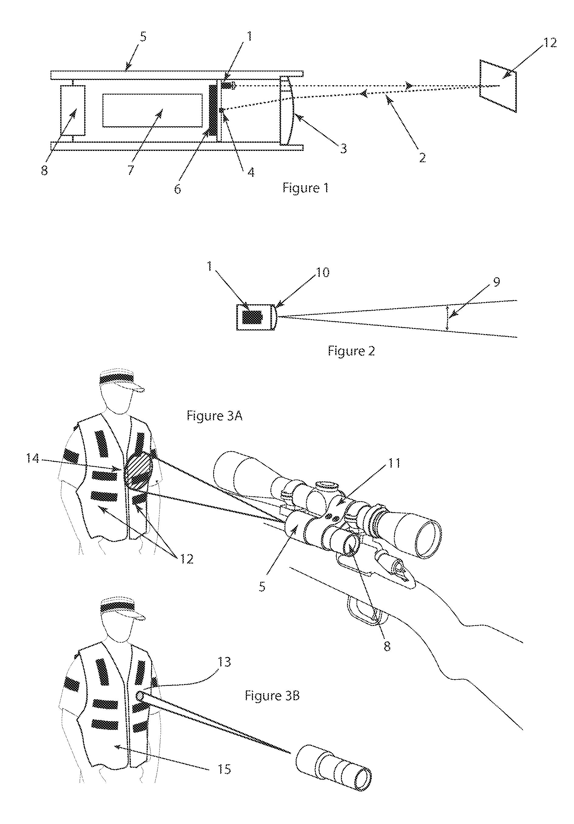
In a preferred embodiment, the present invention relates to a hand-held or “gun / firearm mounted” electromagnetic transceiver acting as a pulsed RADAR (i.e., “Radio Detection and Ranging”) or LIDAR (i.e., “Light Detection and Ranging”) device that can detect the presence of one or many passive retro-reflectors attached to or worn by people or objects that are close or distant in a preferred angle of detection. In a preferred embodiment this device could be mounted on a gun and would alert the user if a retro-reflector is detected in the direction of fire. Additional sensors can be used to change the effective field of detection, to save energy or to provide multiple parallel sensors for these and other reasons.

Description

BACKGROUND OF THE INVENTION[0001]1. Field of the Invention[0002]The present application relates to a system and method for preventing friendly fire accidents.[0003]2. Description of the Prior Art[0004]The present invention relates to a hand-held electromagnetic transceiver acting as a pulsed RADAR (Radio Detection and Ranging) and / or LIDAR (Light Detection and Ranging) device that can detect the presence of one or many objects via passive retro-reflectors that are close or distant in a preferred angle of detection and to ignore any retro-reflector not within that preferred angle of detection.[0005]More particularly, the present invention relates to a system and device to prevent inadvertent targeting and to avoid shooting accidents.BACKGROUND[0006]Examples of target location and direction-finding devices and systems are known in the art, including identification of ‘friend or foe’ (IFF), systems sensitive to movement, proximity sensing, radio location and RADAR / LIDAR, particularly t...

Claims


Application Information

Patent Timeline
Patent Type & Authority Patents(United States)
IPC IPC(8): G08B17/12F41A33/02F41G3/26G01S13/78G01S17/10G01S17/74
CPCG01S17/74F41A33/02G01S13/78F41G3/2661G01S7/489G01S7/34G01S17/10G01S13/10
Inventor SCOTT, MICHAEL
Owner HUNTER SAFETY LAB
Learn More