
Electric system

a technology of electrical systems and components, applied in the field of automatic systems, can solve the problems of insufficient determination of inability to meet the actual current consumption of loads or load groups, etc., to achieve effective monitoring of individual loads and increase fault resilience

Active Publication Date: 2014-09-23
SIEMENS AG
View PDF14 Cites 6 Cited by
  • Summary
  • Abstract
  • Description
  • Claims
  • Application Information

AI Technical Summary

Benefits of technology

This patent is about an improved electrical system that has better protection against faults. One way it does this is by measuring the current consumption of loads connected to the system and adjusting the tripping current of protective devices accordingly. This prevents overload and ensures that only the defective load is disconnected. The system also filters out interference and short load peaks to prevent false triggers, and can adjust its safety margin accordingly based on its operating time. Overall, this invention provides better safety and monitoring of electrical systems.

Problems solved by technology

Due to different requirements, systems of this kind are very rarely implemented in an identical design.
The reason for this resides in the fact that the actual current consumption of the loads or load groups can only be determined to an inadequate degree during the project engineering and configuration phase.
For example, individual control parameters are often not specified until after assembly and installation of the system have been completed, with the result that it is not clear in the preliminary phase which loads, such as solenoid valves, servomotors or contactor coils, will actually be in a switched-on state simultaneously during live operation.
In contrast, too highly dimensioned protective devices, in contrast, generally go unnoticed because not every operating state of every individual load or every individual load group can be taken into consideration, and because of the actual current consumption is measured during an initial startup.
Selective tripping of individual protective devices is no longer ensured because in the event of a short-circuit or an overload it is sometimes no longer the too highly dimensioned, protective device disposed directly upstream of the affected load which trips, but a pre-fuse.
As a result, major parts of the system are disconnected from power unnecessarily.
In the worst case, the capacity of a power source (e.g., 24V control voltage) can be exceeded due to the short-circuit current, resulting in a failure of the entire system.
In addition to the absence of the protective function, it should also be taken into account that too highly dimensioned protective devices do not allow loads to be monitored.
Loads may already be in a partially defective state without the corresponding protective device being tripped.
In a partially defective state, sensors can record or transmit false signals or actuators can fail to perform control functions completely (e.g., a valve will not be fully closed).
A protective device will trip only if there is a significant increase in current as a result of a total failure of the load.

Method used


Image

  • Electric system
  • Electric system
  • Electric system

Examples


Embodiment Construction

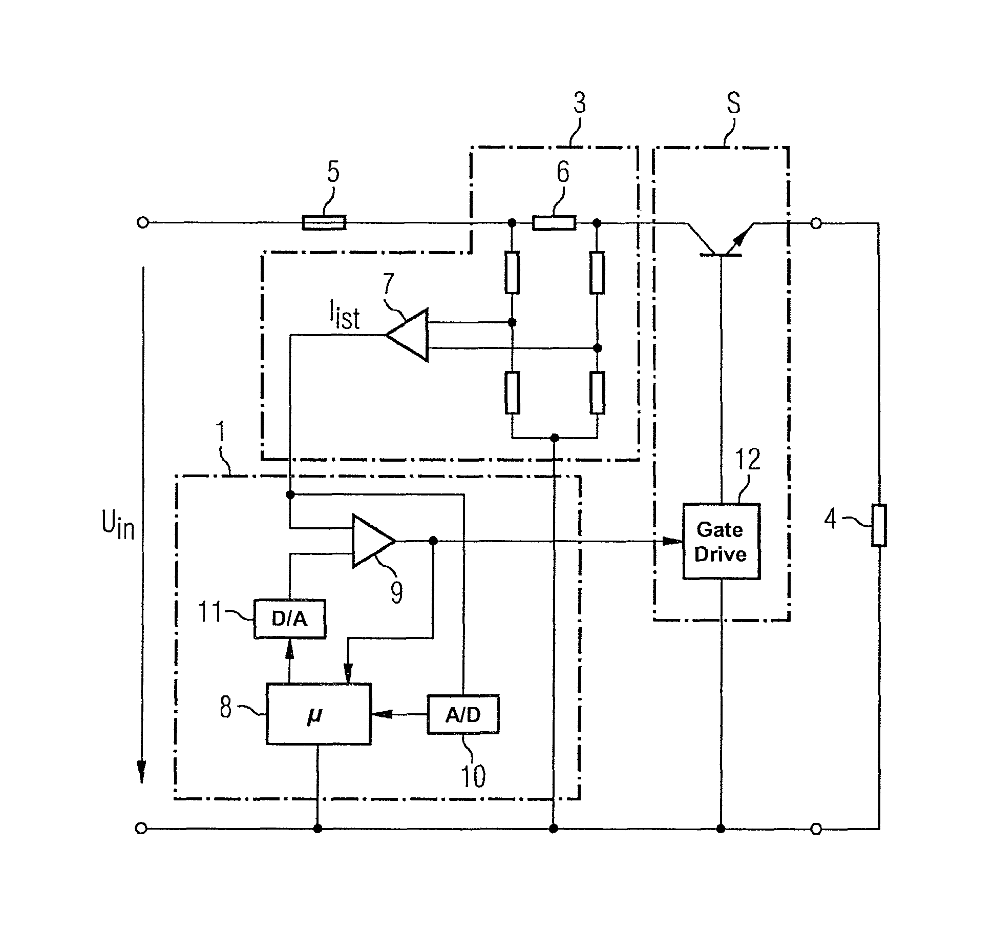
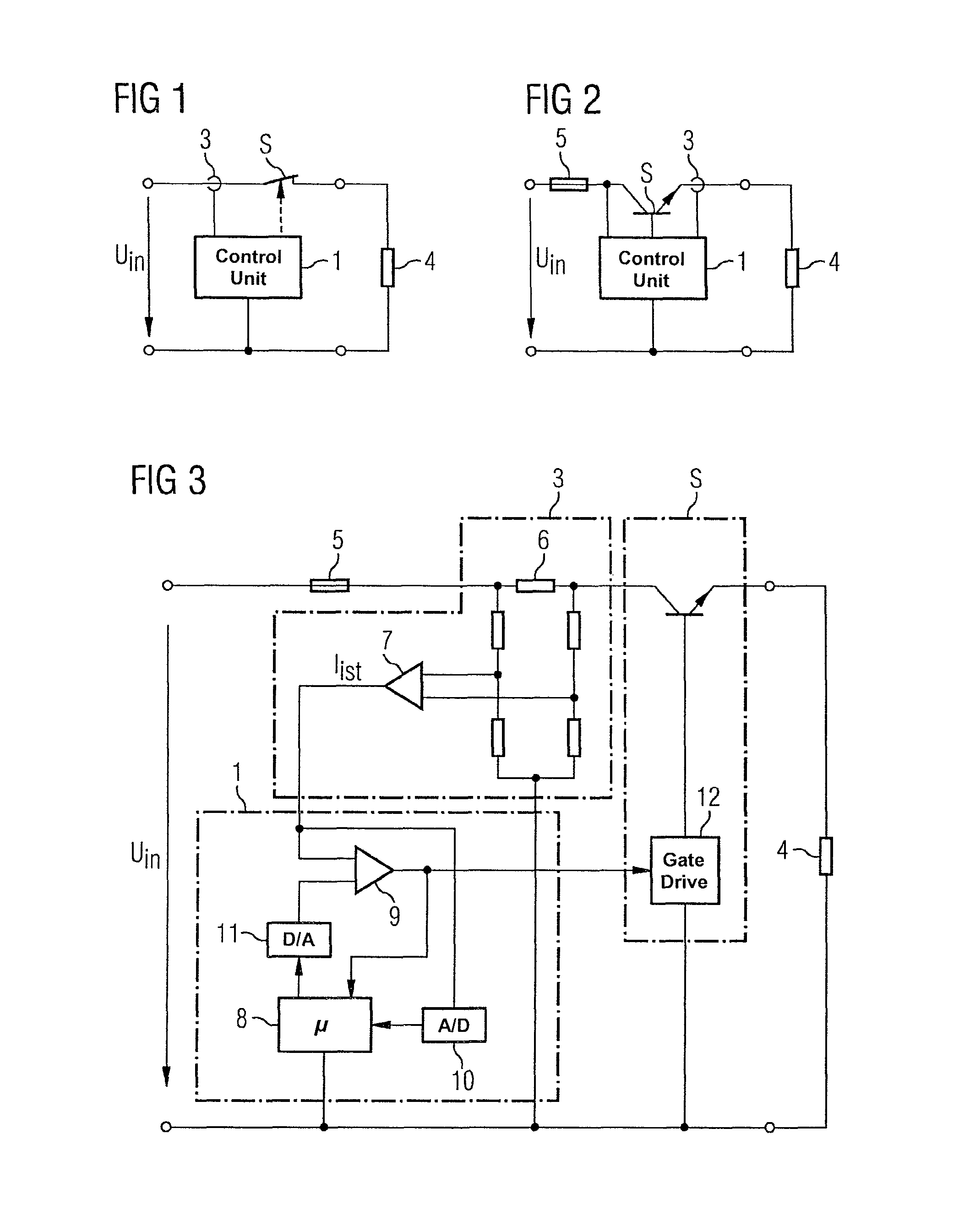
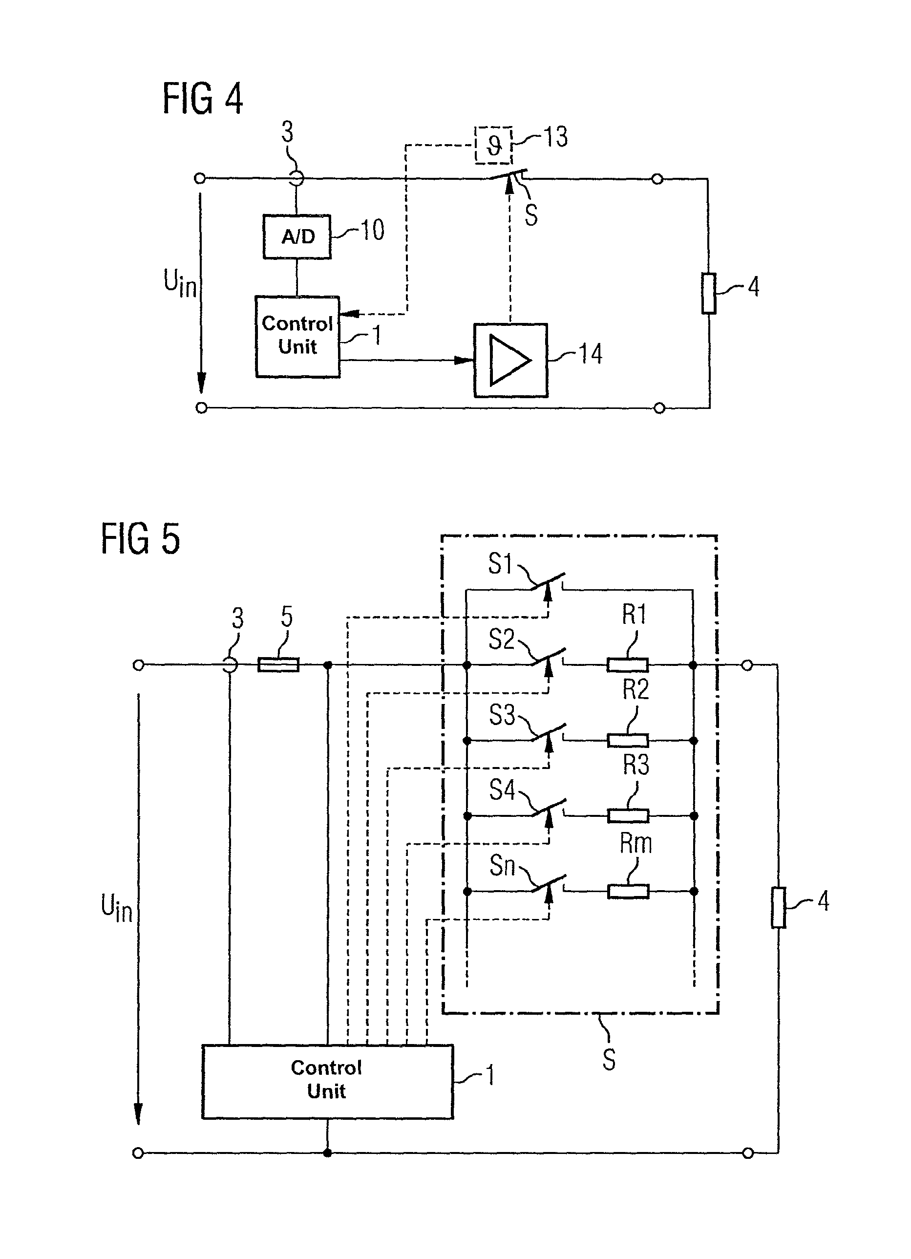
[0049]FIG. 1 shows an embodiment in accordance with the invention. A load 4 is connected to a feed voltage Uin, such as an alternating-current voltage of a power supply network. The feed voltage Uin can, however, also be an output direct-current voltage of a switched-mode power supply. A protective device S is disposed in the power path. In the simplest case the device consists of a mechanical switch which is controlled by a control unit 1.

[0050]The tripping of the protective device S occurs based on predefined tripping conditions, where the corresponding tripping parameters are settable by the control unit 1. Suitable tripping parameters include a value for the tripping current, a maximum permissible duration of an overcurrent or a maximum permissible line temperature. A disconnection or current limiting of the downstream load 4 is then performed if one of the tripping parameters is exceeded.

[0051]In accordance with the invention, at least one tripping parameter of the protective d...


PUM


Abstract

An electrical system having at least one load that is protected by a protective device, where a tripping parameter, i.e., a tripping current of the protective device can be set. A control unit is provided to which a measured current value of the current consumed by the at least one load is supplied, where the control unit generates a limit value, which is provided to the protective device for setting a tripping parameter as a function of the characteristic curve of the measured current value. The control unit thus permits ongoing adjustment of the tripping parameters, i.e., the release current, according to the actual operating conditions.

Description

CROSS-REFERENCE TO RELATED APPLICATIONS[0001]This is a U.S. national stage of International Application No. PCT / EP2009 / 056914, filed on 5 Jun. 2009. This patent application claims the priority of Austria Patent Application No. A1269 / 2008, filed 13 Aug. 2008, the entire content of which application is incorporated herein by reference.BACKGROUND OF THE INVENTION[0002]1. Field of the Invention[0003]The invention relates to automated systems which include a supply circuit having hardwired loads and, more particularly, to an electrical system having at least one current-consuming load that is protected by a protective device, where a tripping parameter, i.e., a tripping current, of the protective device can be set. The invention also relates to a method for operating the electrical system.[0004]2. Description of the Related Art[0005]Typically, automation systems are production systems, process engineering systems or other industrially or commercially usable large-scale installations. Due...

Claims


Application Information

Patent Timeline
Patent Type & Authority Patents(United States)
IPC IPC(8): H02H3/08H02H9/02H02H3/00
CPCH02H3/08H02H3/006H02H1/043
Inventor HUMMEL, ALWINSCHWEIGERT, HARALD
Owner SIEMENS AG
Learn More