
Electret condenser microphone

a condenser microphone and condenser technology, applied in the direction of piezoelectric/electrostrictive transducers, loudspeakers, microphone structural associations, etc., can solve the problems of very important cost considerations, and achieve the effect of low manufacturing cost and good dimensional stability

Active Publication Date: 2014-09-23
INVENSENSE
View PDF16 Cites 5 Cited by
  • Summary
  • Abstract
  • Description
  • Claims
  • Application Information

AI Technical Summary

Benefits of technology

[0010]The exterior sidewall structure may be fabricated in different types of material and associated manufacturing processes. In some embodiments, the exterior sidewall structure may manufactured by injection molding such that the non-conductive base material comprises a thermoplastic resin or compound suitable for injection molding processes. The first and second electrical wiring patterns may subsequently be developed by depositing electrical conductive material inside, or on, wall surfaces of the injection molded non-conductive base material. The exterior sidewall structure may in the alternative be manufactured by insert molding where appropriately shaped electrical conductors are fused into a thermoplastic resin or compound in a mold. In yet another embodiment, the exterior sidewall structure is formed by 3D printing technology such as stereolithography by employing an amount of liquid ultraviolet curable photopolymer “resin” which is illuminated with an ultraviolet laser to build the wall structure in layers one at a time. In yet another embodiment, the exterior sidewall structure comprises a printed circuit board (PCB) such that the non-conductive or insulating base material may comprise FR-4 or similar composite material composed of woven fiberglass with an epoxy resin binder. The printed circuit board sidewall structure is particularly advantageous because conventional PCB fabrication technologies allow the exterior sidewall structure to be manufactured with good dimensional accuracy and stability in large volumes at low-costs.
[0012]In a number of alternative embodiments, the perforated conductive backplate is integrally formed with a lid structure of the closed microphone housing to arrange the conductive perforated backplate above the conductive microphone diaphragm. The lid structure preferably comprises only a single or a few through-going sound ports or inlets for the electret condenser microphone allowing sound to propagate to the conductive microphone diaphragm. Consequently, according to these embodiments, the perforations of the conductive perforated backplate are provided by the single or few through-going sound ports of the lid structure such that the above-mentioned traditional backplate structure placed below the conductive diaphragm is eliminated. The traditional backplate structure may induce an undesired acoustic resistance to the electroacoustic characteristics of the microphone which leads to additional microphone noise.
[0013]The lid structure is preferably formed as a separate member which is attached to an upper circumferential edge of the sidewall structure during microphone manufacturing such that the integrally formed conductive perforated backplate is placed in the desired spatial relationship to the conductive microphone diaphragm across an intervening air gap. The lid structure may conveniently comprise a substantially flat printed circuit board having an inwardly facing metallized surface supporting the electret layer. The metallized layer is coupled to the second wiring pattern of the exterior sidewall structure. This lid structure can be manufactured by the application of ordinary PCB manufacturing technologies leading to numerous advantages as described in additional detail below. The electret layer may comprise a thin Teflon film bonded to the inwardly facing metallized surface of the flat printed circuit board of the lid structure.
[0017]The skilled person will understand that at least one of the carrier, the sidewall structure and the lid structure preferably comprises a single-layer or multi-layer printed circuit board. In certain embodiments, each of the carrier, the sidewall structure and the lid structure comprises a printed circuit board. The use of the same type of material for the fabrication of the carrier, the sidewall structure and the lid structure leads to low manufacturing costs. In addition, the ECM design will possess good dimensional stability due to the elimination of differences in thermal expansion coefficients of different components of the ECM.

Problems solved by technology

Miniature ECMs are sold in very large quantities for numerous highly cost-sensitive consumer applications which make costs considerations very important.

Method used


Image

  • Electret condenser microphone
  • Electret condenser microphone
  • Electret condenser microphone

Examples


first embodiment

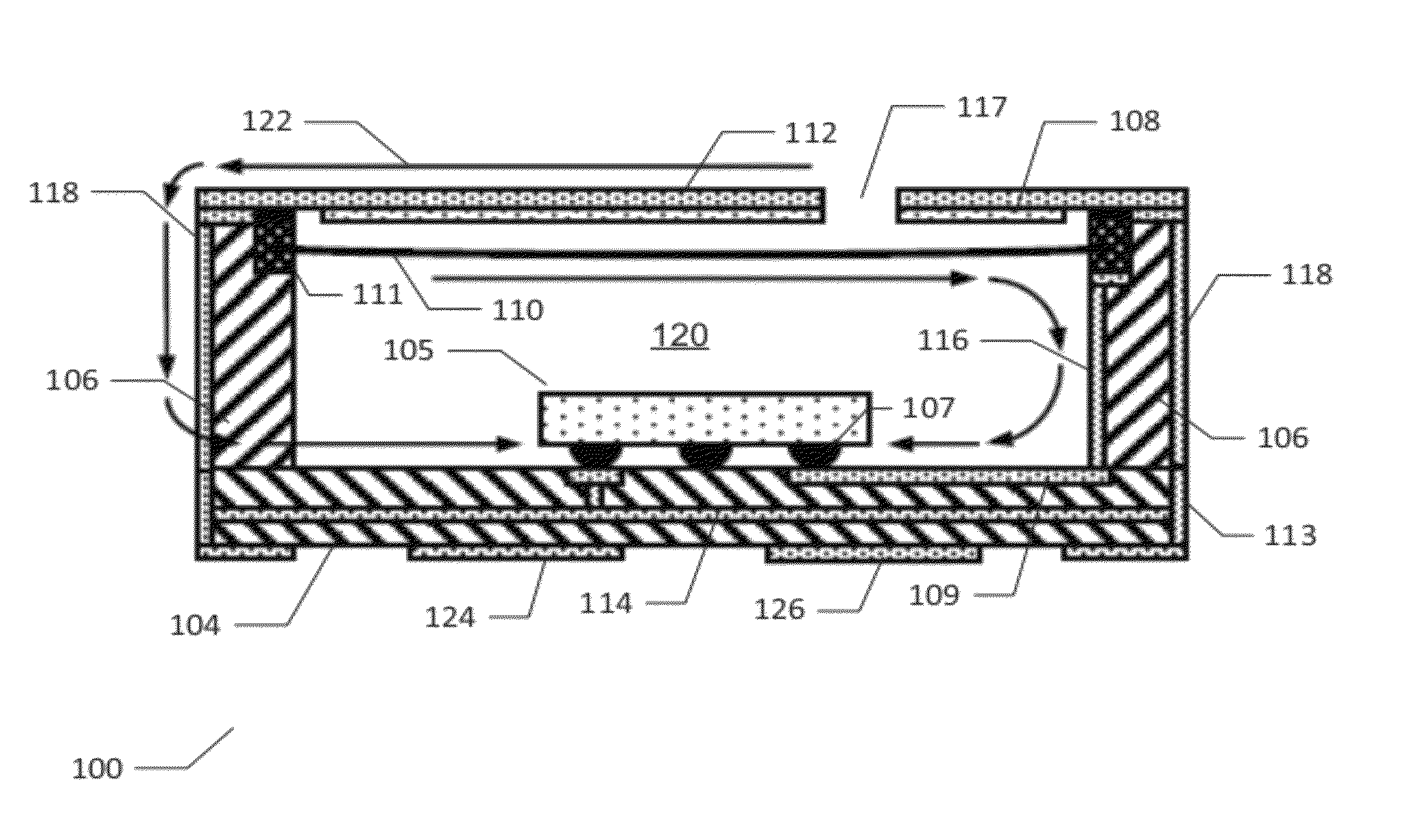
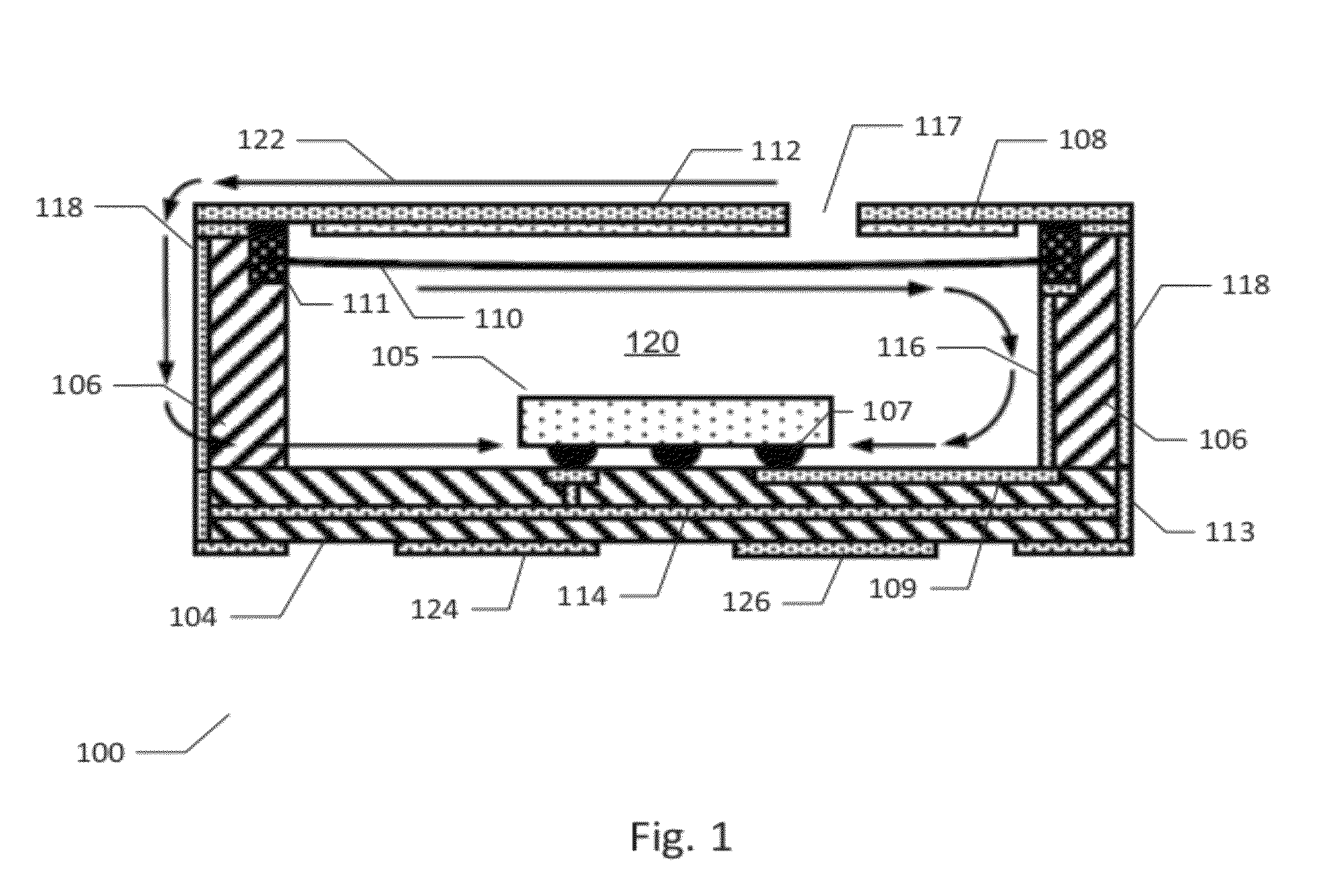
[0029]FIG. 1 is a vertical cross-sectional view of an electret condenser microphone (ECM) 100 according to the invention. The ECM 100 comprises a carrier 104 that may comprise a single layer or multi-layer printed circuit board or a ceramics substrate. The carrier 104 comprises first and second mutually insulated electrical traces or wires. The first electrical trace 109 is disposed on an upper surface of the carrier 104 also carrying or supporting a microphone preamplifier 105. A microphone preamplifier is provided on a semiconductor die or substrate 105. The microphone preamplifier may be integrated on an Application Specific Integrated Circuit (ASIC) fabricated in a sub-micron CMOS semiconductor process technology. The semiconductor die 105 is attached to the upper surface of the carrier 104 through a set of preamplifier pads or terminals which mate to a set of carrier pads A first preamplifier terminal 107 is an audio input of the microphone preamplifier 105 and the audio input ...

second embodiment

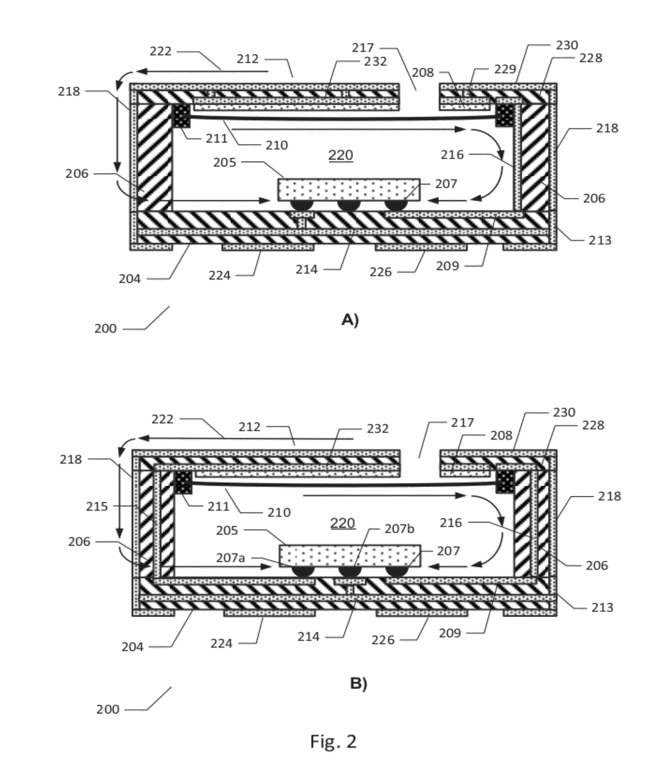
[0037]FIG. 3 is a schematic exploded view of the ECM 200 described above in accordance with the invention. The ECM housing is formed exclusively by three separate members, i.e. the carrier 204, the exterior sidewall structure 206 and the lid structure 212 which jointly form a substantially closed microphone housing. Furthermore, each of the carrier 204, the exterior sidewall structure 206 and the lid structure 212 is preferably fabricated in PCB material using conventional PCB manufacturing processes and technology to provide a low-cost housing structure. Furthermore, electrical wiring patterns provided on the outside surfaces of, or inside, the exterior sidewall structure 206 provide electrical interconnection between the conductive microphone diaphragm 210 (refer to FIG. 2) and the backplate structure, formed integrally with the lid structure 212, and the microphone preamplifier integrated on the ASIC 205. The adaptation of the exterior sidewall structure 206 to provide this type ...


PUM

PropertyMeasurementUnit
lengthaaaaaaaaaa
lengthaaaaaaaaaa
impedanceaaaaaaaaaa

Abstract

The present invention relates to an electret condenser microphone which comprises an exterior sidewall structure attached to a carrier. The exterior sidewall structure comprises a non-conductive base material carrying first and second electrical wiring patterns electrically connected to first and second electrical traces, respectively, of the carrier. A diaphragm holder, carrying a conductive microphone diaphragm is attached to the sidewall structure to establish electrical connection between a conductive microphone diaphragm and one of the first and second electrical wiring patterns of the sidewall structure. A conductive perforated backplate is arranged in spaced relationship to the conductive microphone diaphragm. The conductive perforated backplate is electrically connected to another one of the first and second wiring patterns of the sidewall structure. The sidewall structure may therefore be utilized to provide electrical connectivity from the conductive microphone diaphragm and from the backplate to a microphone preamplifier arranged on the carrier.

Description

[0001]The present invention relates to an electret condenser microphone which comprises an exterior sidewall structure attached to a carrier. The exterior sidewall structure comprises a non-conductive base material carrying first and second electrical wiring patterns electrically connected to first and second electrical traces, respectively, of the carrier. A diaphragm holder, carrying a conductive microphone diaphragm is attached to the sidewall structure to establish electrical connection between a conductive microphone diaphragm and one of the first and second electrical wiring patterns of the sidewall structure. A conductive perforated backplate is arranged in spaced relationship to the conductive microphone diaphragm. The conductive perforated backplate is electrically connected to another one of the first and second wiring patterns of the sidewall structure. The sidewall structure may therefore be utilized to provide electrical connectivity from the conductive microphone diaph...

Claims


Application Information

Patent Timeline
Patent Type & Authority Patents(United States)
IPC IPC(8): H04R25/00H04R17/02H04R19/04H04R21/02H04R11/04H04R1/00H04R11/02H04R9/06H04R1/04H04R19/01
CPCH04R1/04H04R19/016H04R2201/029Y10T29/49005B33Y80/00H01L2224/16225
Inventor LILLELUND, CHRISTIAN
Owner INVENSENSE
Learn More