Micro-spiral implantation device

a micro-spiral and implantation device technology, applied in the field of micro-spiral implantation devices, can solve the problems of threatening embolism, polymer threads may suddenly break, and the micro-spiral is not restricted, and achieves the effects of less rigidity, high stress, and no angular displacemen

Active Publication Date: 2014-09-30
TYCO HEALTHCARE GRP LP
View PDF124 Cites 19 Cited by
  • Summary
  • Abstract
  • Description
  • Claims
  • Application Information

AI Technical Summary

Benefits of technology

[0026]Preferably, the securing means of the device according to the invention is a little longer than the particular portion of the microcoil along which it extends. The length of the securing means established in this manner results in a less rigid arrangement in spite of the attachment or fixation inside the microcoil so that in the absence of external forces being exerted the securing means in the microcoil is not subjected to tensile stresses and the flexibility of the microcoil is not restricted. The securing means may as well extend over the entire length of the occlusion helix from the proximal to the distal end without having to make sacrifices in movability and flexibility so that in this way the entire occlusion helix can be secured by preventing it from being torn off. Since the distal tip of an occlusion helix is subjected to particularly high stresses when the helix is placed into a blood vessel the securing means should in fact extend up to the distal tip section of the occlusion helix.

Problems solved by technology

Maneuvers of this kind involve risks in that parts of the helix are pulled apart and elongated due to the tensile or torsional stresses applied, and in this way become plastically deformed irreversibly, are torn off or broken which may give rise to life-threatening embolism.
However, this prior-art technique has the disadvantage in that the polymer thread may suddenly break in the event that too high a retraction force is exerted.
In such a case the entire tensile load suddenly acts on the occlusion helix itself which may cause not only deformation but may even lead to occlusion helix breakage.
Since such a break of the polymer thread may occur all of a sudden the detrimental effects caused in the blood vessel may be considerable and can hardly be controlled.

Method used


Image

  • Micro-spiral implantation device
  • Micro-spiral implantation device
  • Micro-spiral implantation device

Examples


Embodiment Construction

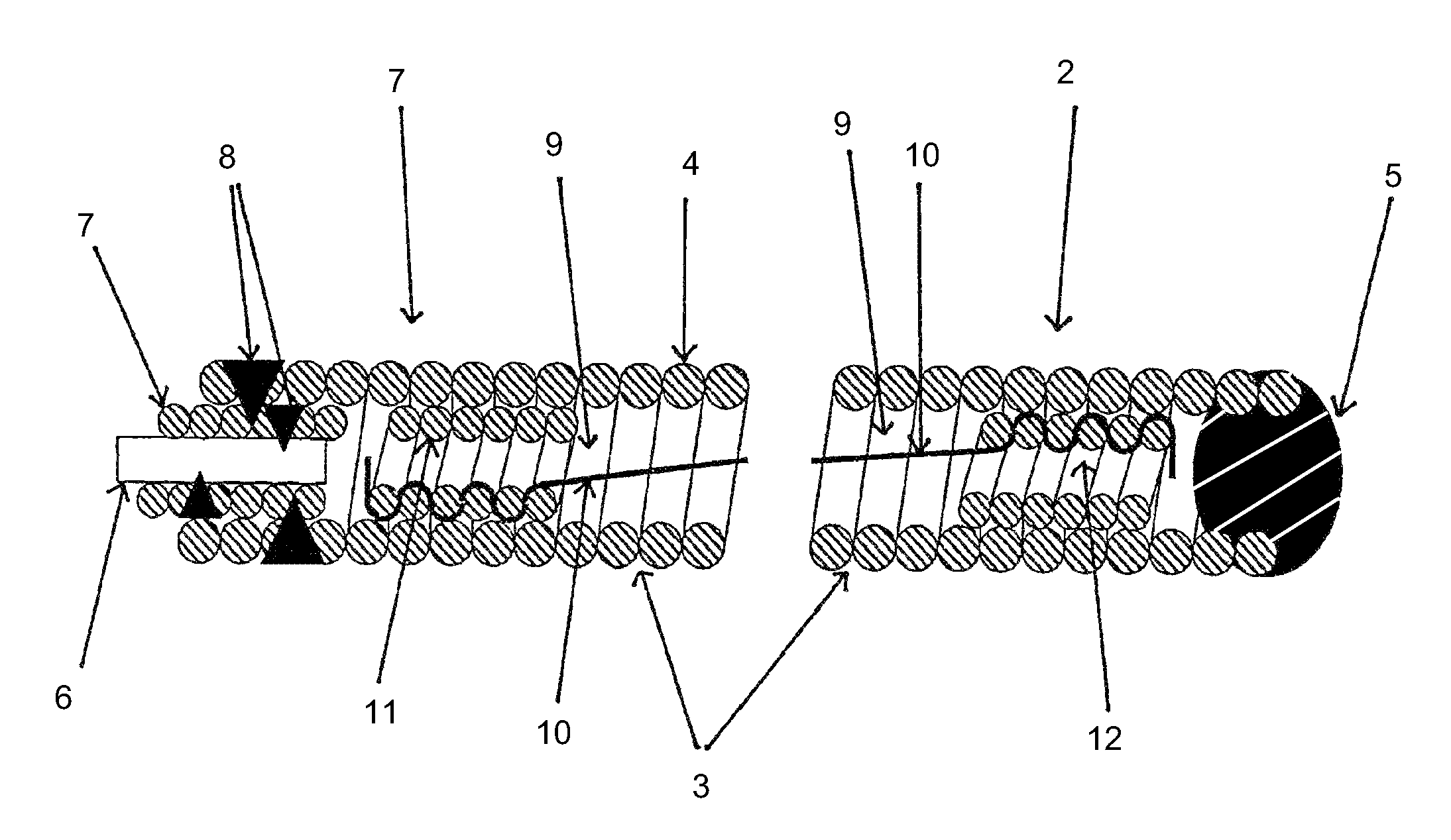
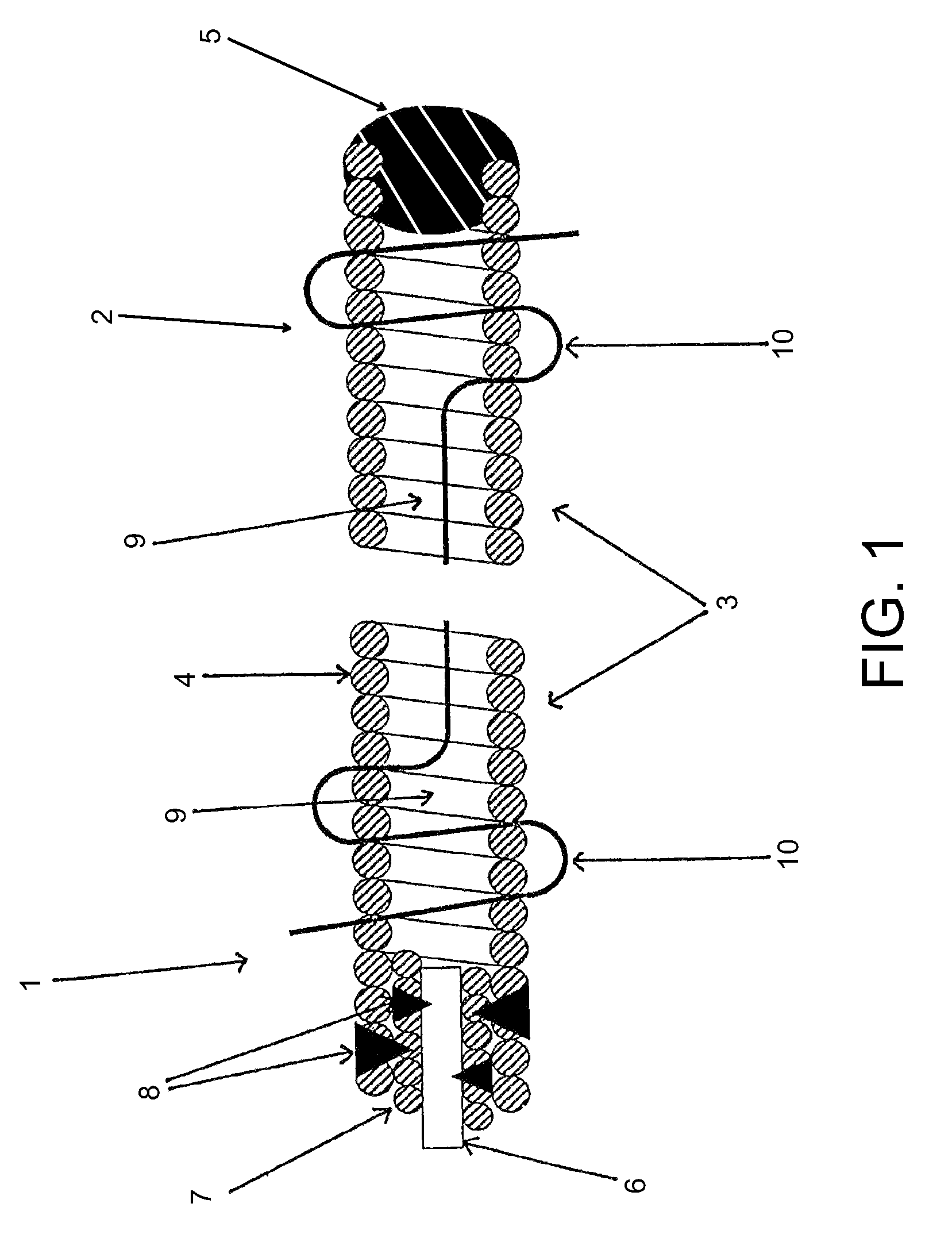
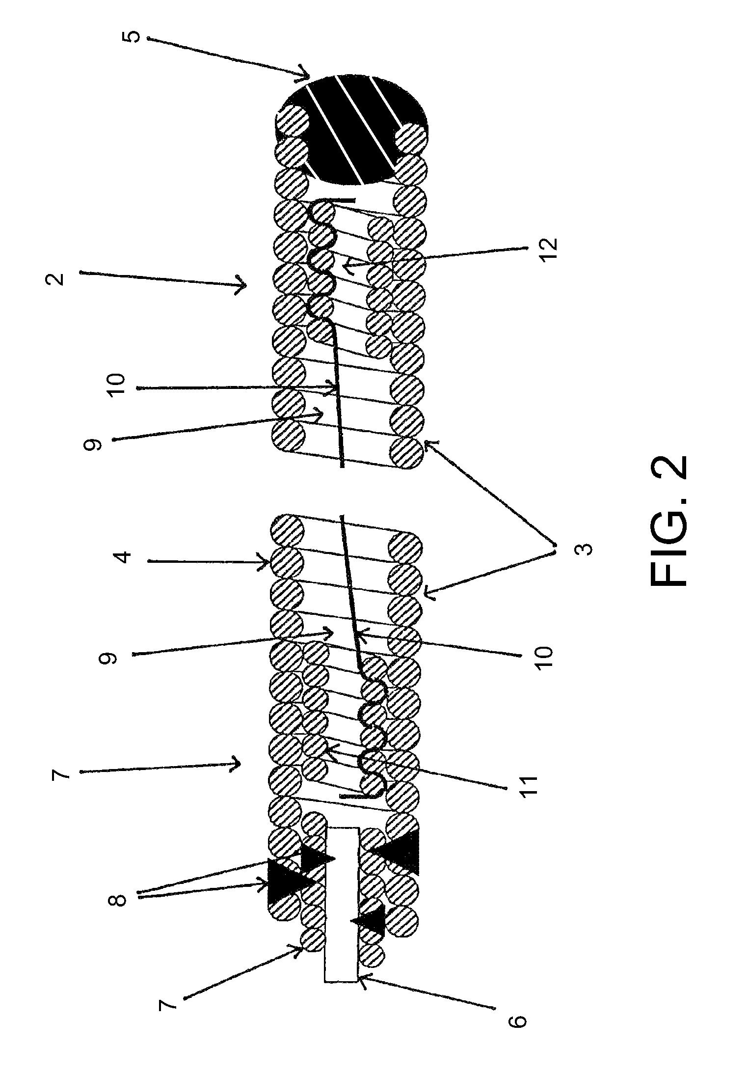
[0034]From FIG. 1 the proximal area 1 and the distal area 2 of an occlusion helix 3 can be seen shown as a longitudinal section. The occlusion helix 3 shown here consists of a wire comprising a plurality of windings 4. The distal tip 5 of the occlusion helix 3 is rounded with a view to minimizing aneurysm traumatizing risks. Proximally to the occlusion helix 3 there is a severance element 6 which extends through a microcoil 7 additionally incorporated into the occlusion helix 3. The connection between the additional microcoil 7 and the occlusion helix 3 and between severance element 6 and additional microcoil 7 is made by providing joining points 8, for which purpose various techniques may be employed such as soldering, welding, bonding or mechanical joining methods. The severance element 6 is designed so as to be electrolytically corrodible to enable the occlusion helix 3 by applying a voltage to be released and placed into the aneurysm.

[0035]A polymer thread extends through the lu...


PUM


Abstract

The invention relates to a device for the implantation of microcoils (3, 7, 11, 12) into body cavities and blood vessels, in particular aneurysms, with said microcoils (3, 7, 11, 12) comprising wires forming a plurality of windings (4), at least one microcoil serving as occlusion helix (3) for the occlusion of the body cavity or blood vessel, and the device consisting of a catheter, one or several microcoils (3, 7, 11, 12) movably arranged in longitudinal direction within the catheter and at least one securing means (10) passing at least partially through the lumen (9) of the occlusion helix (3), with said securing means (10) being fixed in its end areas inside the microcoils (3, 7, 11, 12). Such a fixation of the securing means (10) is achieved in at least one end area by providing a frictional connection with the microcoil (3, 7, 11, 12) in such a manner that this connection is detachable from the microcoil (3, 7, 11, 12) when a certain tensile force acting on the securing means (10) is exceeded. In this way, a sudden breakage of the securing means (10) is avoided if too high a pull force is applied so that forces otherwise liberated cannot destroy the occlusion helix (3) or cause other damage in the blood vessel.

Description

BACKGROUND OF THE INVENTION[0001]The invention relates to a device for the implantation of microcoils into body cavities and blood vessels, in particular aneurysms, with the microcoils comprising wires forming a plurality of windings, at least one microcoil serving as occlusion helix for the occlusion of the body cavity or blood vessel, and the device consisting of a catheter, one or several microcoils movably arranged in longitudinal direction within the catheter and at least one securing means passing at least partially through the lumen of the occlusion helix, with the securing means being fixed in its end areas inside the microcoils. Furthermore, the invention relates to an occlusion helix to be used in connection with the aforedescribed device.[0002]The use of endovascular techniques for the occlusion of body cavities or vessels such as arteries, veins, fallopian tubes or vascular deformities (for example, vascular aneurysms) is known in the art. In this case, the occlusion hel...

Claims


Application Information

Patent Timeline
Patent Type & Authority Patents(United States)
IPC IPC(8): A61M29/00A61B17/12
CPCA61B17/12022A61B17/1215A61B2017/12063
Inventor MONSTADT, HERMANNFLESSER, ACHIMHANNES, RALF
Owner TYCO HEALTHCARE GRP LP
Why Eureka
Try Eureka