Vehicle and method of controlling the same

a technology of vehicle and shifting operation, applied in the direction of battery/cell propulsion, process and machine control, instruments, etc., can solve the problems of unsatisfactory output response or responsiveness of the driving force for running the vehicle to a shifting operation performed by the driver, and drivers may feel unsatisfactory with the acceleration feeling of the vehicle, so as to improve energy efficiency and output characteristic of the driving force for running the vehicle in response to a shifting operation

Active Publication Date: 2014-09-30
TOYOTA JIDOSHA KK
View PDF6 Cites 0 Cited by
  • Summary
  • Abstract
  • Description
  • Claims
  • Application Information

AI Technical Summary

Benefits of technology

[0007]The invention provides a vehicle including at least an electric motor capable of delivering power to a drive shaft coupled to driving wheels and an electric storage device capable of supplying and receiving electric power to and from the electric motor, in which the output characteristic of driving force for running the vehicle in response to a shifting operation is improved, and the energy efficiency is improved through shifting operations.
[0011]In the vehicle according to the above aspect of the invention, the restriction storing device stores the plurality of restrictions created so that, in each of the virtual gear ranges, the required driving force as driving force to be applied to the drive shaft, which corresponds to the same accelerator operation amount, tends to be increased as the vehicle speed is higher, and the required driving force corresponding to the same accelerator operation amount tends to be increased as the virtual gear range is shifted to a lower range when the vehicle speed is constant. When one of the virtual gear ranges is selected by the driver, the required driving force corresponding to the accelerator operation amount obtained by the accelerator operation amount obtaining device and the vehicle speed obtained by the vehicle speed obtaining device is set, using the restriction corresponding to the selected virtual gear range, and the electric motor is controlled so that power based on the required driving force is delivered to the drive shaft. With the plurality of restrictions as described above thus created for the respective virtual gear ranges, the output response of the driving force for running the vehicle is enhanced as the vehicle speed is higher when a certain virtual gear range is selected, and the output response of the driving force for running the vehicle is enhanced as the virtual gear range is shifted to a lower range in a condition where the vehicle speed is constant. It is thus possible to accelerate the vehicle with the enhanced output response of the driving force for running the vehicle, by setting one of the virtual gear ranges as the gear range, or shifting the virtual gear range to a lower range. Also, with the above-described restrictions thus created for the respective virtual gear ranges, the increase of the required driving force is restricted to a larger extent as the vehicle speed is lower when a certain virtual gear range is selected, and the increase of the required driving force is restricted to a larger extent as the virtual gear range is shifted to a higher range while the vehicle speed is constant. It is thus possible to reduce or restrict the output of the driving force for running the vehicle and improve the energy efficiency of the vehicle, by setting one of the virtual gear ranges as the gear range, or shifting the virtual gear range to a higher range. Accordingly, in the vehicle according to the above aspect of the invention, the output characteristic of the driving force for running the vehicle in response to a shifting operation can be improved, and the energy efficiency can be improved through shifting operations.
[0013]According to the above aspect of the invention, the output characteristic of the driving force for running the vehicle in response to a shifting operation can be improved, and the energy efficiency can be improved through shifting operations.

Problems solved by technology

However, the output response or responsiveness of the driving force for running the vehicle to a shifting operation performed by the driver is not always satisfactory if only the lower limit of the engine speed is set based on the virtual shift position and the vehicle speed as in the hybrid vehicle as described above.
For example, some drivers may feel unsatisfied with the acceleration feeling of the vehicle responsive to a shifting operation.

Method used


Image

  • Vehicle and method of controlling the same
  • Vehicle and method of controlling the same
  • Vehicle and method of controlling the same

Examples


Embodiment Construction

[0029]One mode for carrying out the invention will be described as an embodiment of the invention.

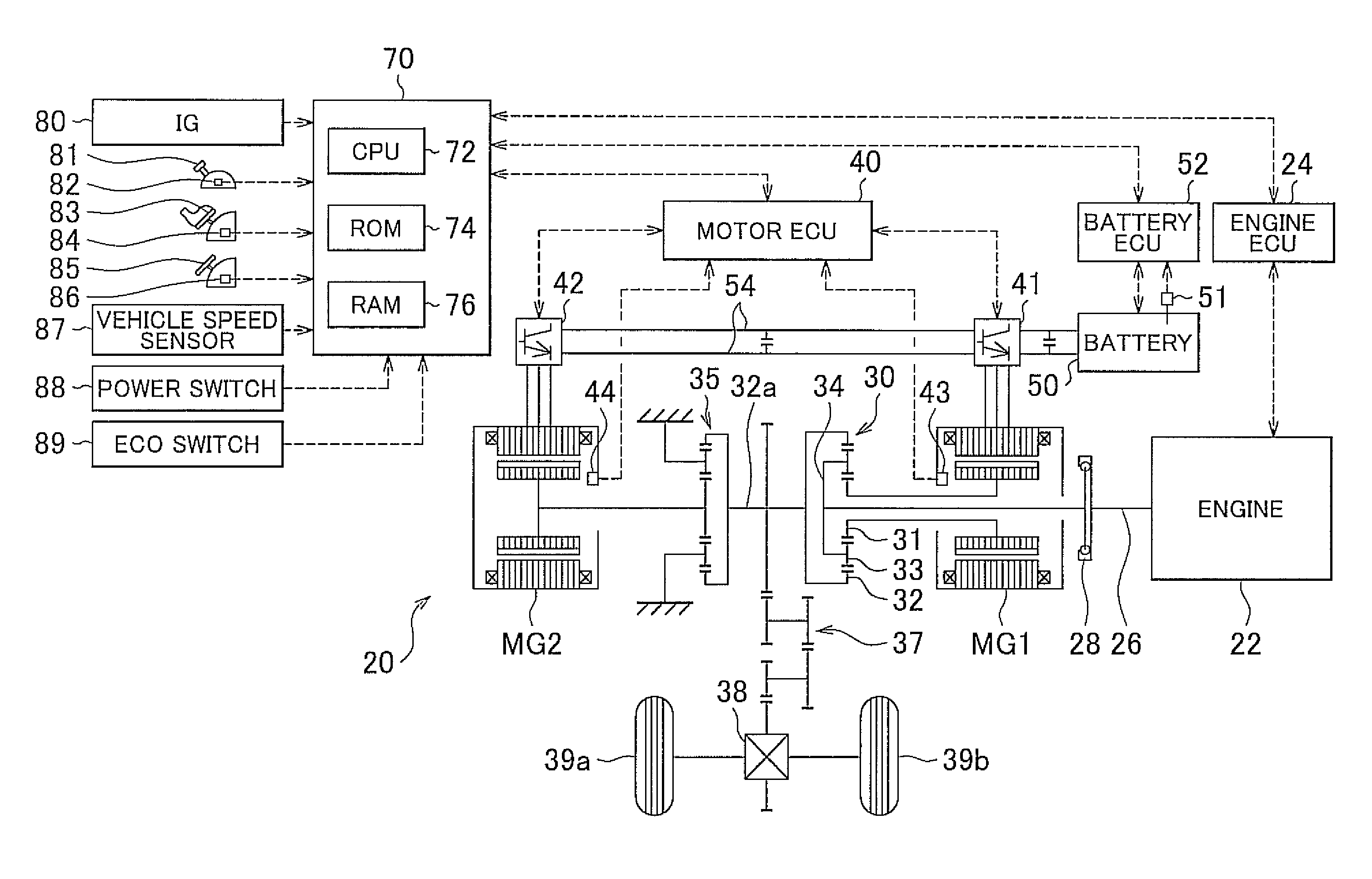
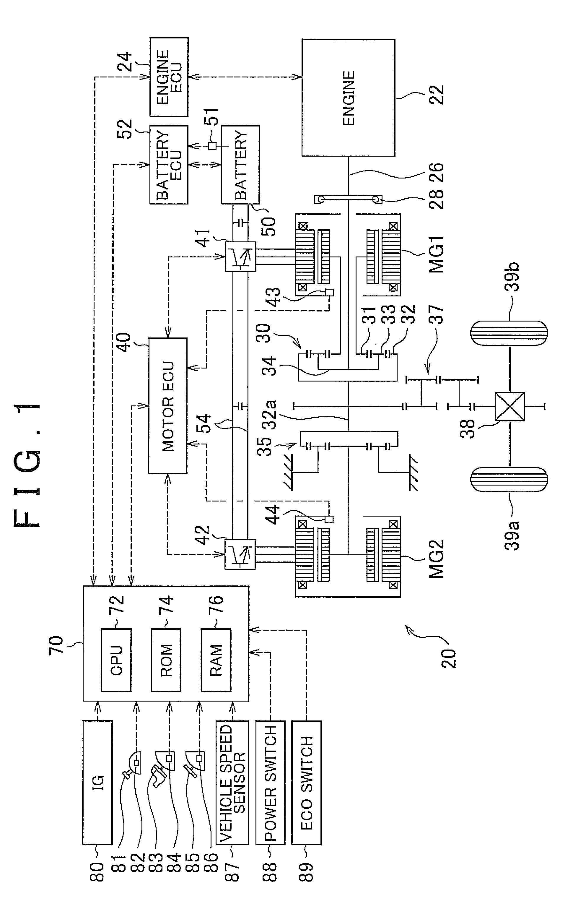
[0030]FIG. 1 is a schematic view showing the construction of a hybrid vehicle 20 as a vehicle according to the embodiment of the invention. The hybrid vehicle 20 shown in FIG. 1 includes an engine 22, a three-shaft-type power distribution and integration mechanism 30 connected to a crankshaft 26 as an output shaft of the engine 22 via a damper 28, a motor MG1 connected to the power distribution and integration mechanism 30 and capable of generating electric power, a reduction gear 35 coupled to a ring gear shaft 32a as a drive shaft connected to the power distribution and integration mechanism 30, a motor MG2 connected to the ring gear shaft 32a via the reduction gear 35, a battery 50 capable of supplying and receiving electric power to and from the motors MG1 and MG2, an electronic control unit for hybrid vehicles (hereinafter called “hybrid ECU”) 70 that controls the overall system of...


PUM


Abstract

A vehicle has a restriction storing device that stores a plurality of restrictions that are respectively created for a plurality of virtual gear ranges, such that, in each of the virtual gear ranges, required driving force as driving force to be applied to a drive shaft corresponding to the same accelerator operation amount tends to be increased as the vehicle speed is higher, and the required driving force corresponding to the same accelerator operation amount tends to be increased as the virtual gear range is shifted to a lower range when the vehicle speed is constant.

Description

CROSS-REFERENCE TO RELATED APPLICATIONS[0001]This application claims priority to Japanese Patent Application No. 2010-028825 filed on Feb. 12, 2010, which is incorporated herein by reference in its entirety including the specification, drawings and abstract.BACKGROUND OF THE INVENTION[0002]1. Field of the Invention[0003]The invention relates to a vehicle including at least an electric motor capable of delivering power to a drive shaft coupled to driving wheels and electric storage means capable of supplying and receiving electric power to and from the electric motor, and a method of controlling the vehicle.[0004]2. Description of the Related Art[0005]A hybrid vehicle is known which includes an engine, a planetary gear mechanism having a planetary carrier connected to a crankshaft of the engine and a ring gear connected to a drive shaft coupled to driving wheels, a first motor connected to a sun gear of the planetary gear mechanism, and a second motor connected to the drive shaft, an...

Claims


Application Information

Patent Timeline
Patent Type & Authority Patents(United States)
IPC IPC(8): B60L9/00B60W10/00B60W10/08B60K6/365B60K6/445B60K6/54B60L15/20B60L50/15B60L50/16B60W10/06B60W10/10B60W10/115B60W20/00B60W30/19F02D29/02
CPCB60L11/123B60W20/00B60K6/445B60W10/08B60K6/365B60W10/06B60L11/14B60W10/115B60L15/2054Y02T10/648B60W2520/10B60W2540/16Y02T10/6217Y02T10/6239Y02T10/7077Y02T10/6286B60W2540/10B60W2710/083Y02T10/7258Y02T10/646B60W30/19Y02T10/70Y10S903/93Y02T10/7275B60L50/61B60L50/16Y02T10/62Y02T10/64Y02T10/7072Y02T10/72B60W30/188B60L15/20
Inventor YAMAMOTO, KOJI
Owner TOYOTA JIDOSHA KK
Why Eureka
Try Eureka