Trigger-based data collection system

a data collection and trigger technology, applied in the direction of instruments, signalling indicators on vehicles, transportation and packaging, etc., can solve the problems of large transmission volume, system and method disclosure may still suffer from a number of possible drawbacks, and difficulty in determining which subsystem is suffering

Active Publication Date: 2014-09-30
ELECTRO-MOTIVE DIESEL
View PDF15 Cites 54 Cited by
  • Summary
  • Abstract
  • Description
  • Claims
  • Application Information

AI Technical Summary

Problems solved by technology

In complex machines with multiple subsystems, it may be difficult to determine which subsystem is suffering from a fault or the particular cause of that fault without extensive analysis of the affected machine.
Although the system and method disclosed in the '478 patent may monitor and report operational data of a machine, the system and method disclosed may still suffer from a number of possible drawbacks.
In complex machines such as locomotives, this may result in transmission of a significantly large amount of data, a large portion of which may be wholly unrelated to the fault condition that triggered the data collection or transmission.

Method used


Image

  • Trigger-based data collection system
  • Trigger-based data collection system
  • Trigger-based data collection system

Examples


Embodiment Construction

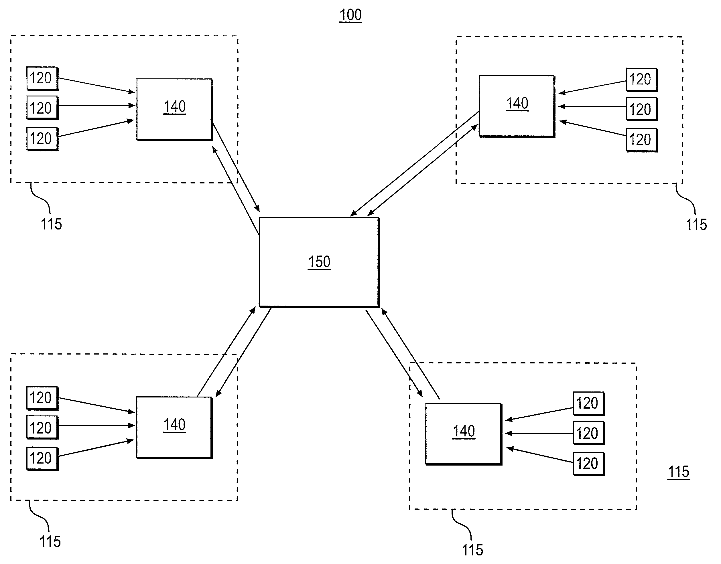
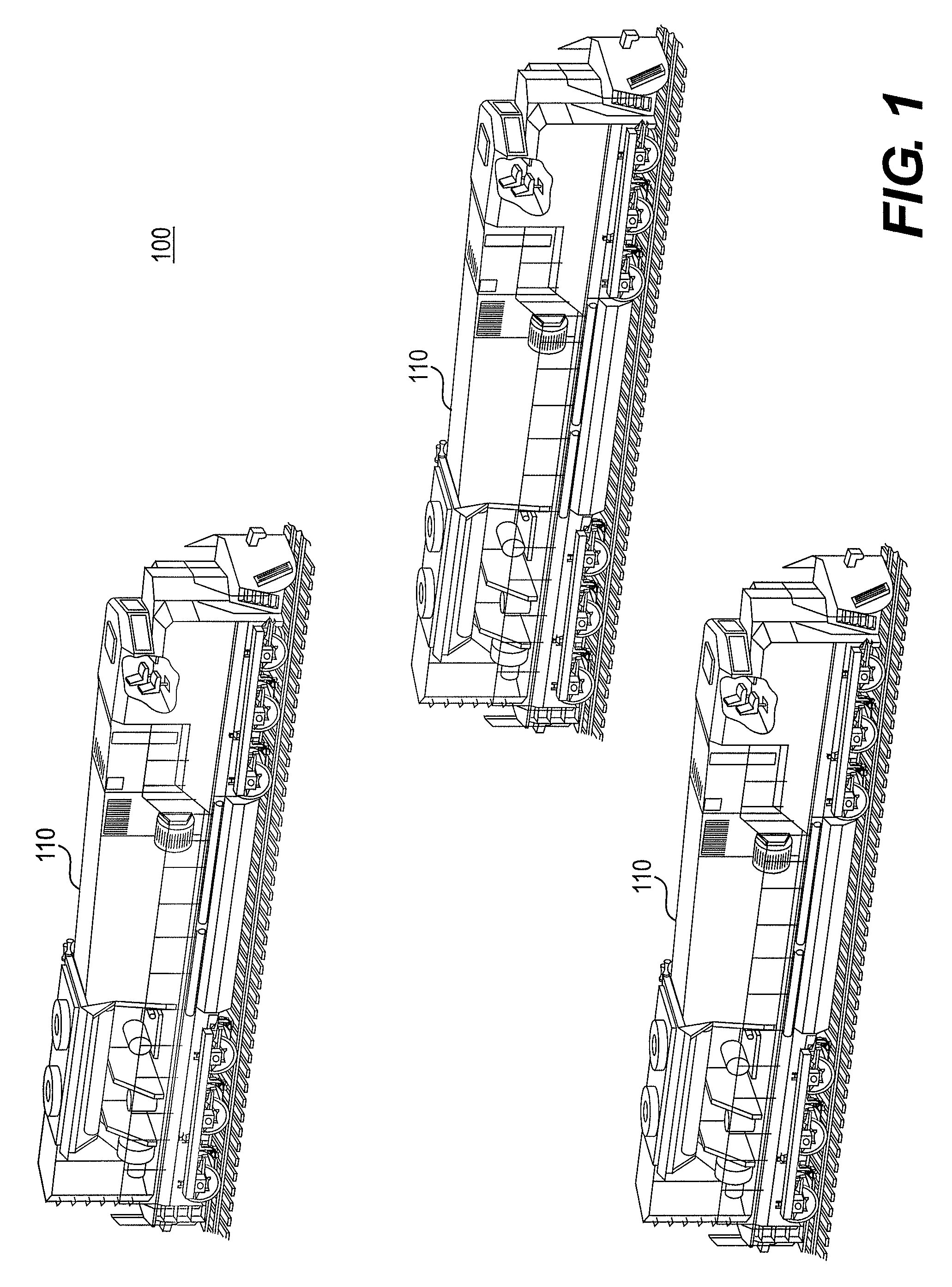
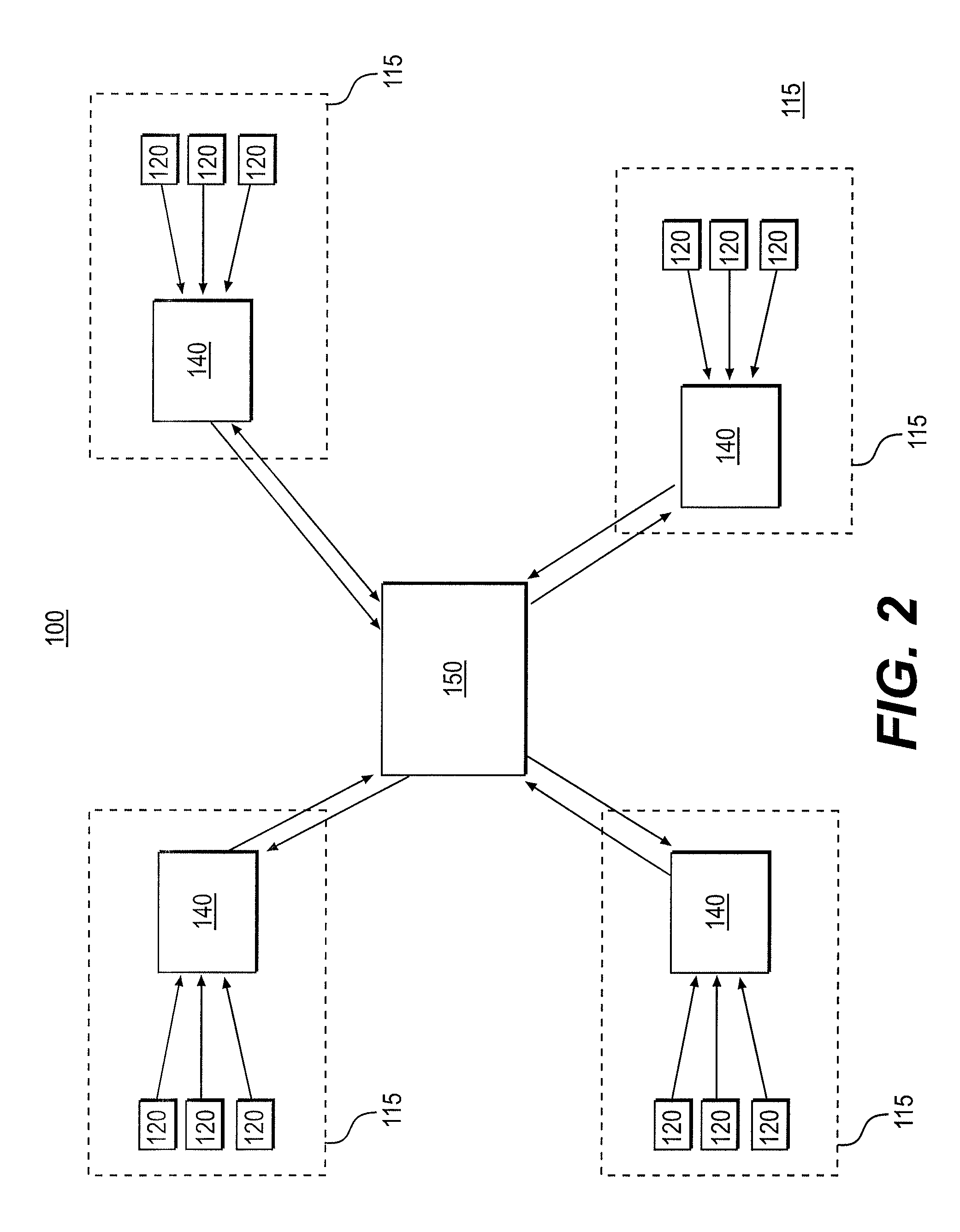
[0013]FIG. 1 shows an exemplary machine fleet 100 in which systems and methods for data collection may be implemented consistent with the disclosed embodiments. Machine fleet 100 may include any group of machines 110 defined by shared or similar characteristics. According to some embodiments, each machine 110 of machine fleet 100 may be the same type or the same model of machine. For example, the three machines 110 comprising the exemplary machine fleet 100 shown in FIG. 1 are all locomotives. Machine fleet 100 may include other types of machines, including but not limited to fixed engine systems, construction machines, commercial machines, and marine-based machines, that may incorporate the systems and methods for data collection consistent with the embodiments disclosed herein.

[0014]A machine fleet 100 may be defined by shared or similar characteristics among the plurality of machines 110 of machine fleet 100. It may be desirable to define machine fleet 100 based on a common chara...


PUM


Abstract

A system for collecting and communicating data associated with at least one of a plurality of machines includes a sensor. The sensor is configured to monitor an operational condition of the at least one associated machine and provide signals indicative of the operational condition. The system includes at least one local data system, including a processor, associated with the machine and configured to receive signals from the sensor, detect an event affecting the at least one machine based on the signals received from the sensor, and communicate data relevant to the detected event to a location remote from the at least one machine. A central data system including a processor and configured to receive the data relevant to the detected event and communicate with other machines of the plurality of much such that the other machines communicate data relevant to the detected event to the central data system is included.

Description

TECHNICAL FIELD[0001]This disclosure relates generally to systems and methods monitoring operation and fault conditions of a machine, and more specifically, to systems and methods for collecting and communicating data associated with a fleet of machines in response to a triggering event.BACKGROUND[0002]Machine downtime suffered as a result of a fault condition in a machine such as, for example, a locomotive, can be costly, so efficient diagnostics systems are desirable to minimize repair time. In complex machines with multiple subsystems, it may be difficult to determine which subsystem is suffering from a fault or the particular cause of that fault without extensive analysis of the affected machine.[0003]For maintenance and diagnostic purposes, it may be desirable to collect data relating to a machine during real-time operation for later retrieval. In some diagnostic systems, the data collected often includes much more information than what may be desired for a specific purpose or ...

Claims


Application Information

Patent Timeline
Patent Type & Authority Patents(United States)
IPC IPC(8): G06F15/173
CPCB61L15/0081B61L27/0094H04L67/04G06F11/30B61L27/57
Inventor COLLINS, PAUL FRANCISMARTIN, MICHAEL SHAWN
Owner ELECTRO-MOTIVE DIESEL
Why Eureka
Try Eureka