Inkjet image forming apparatus
a technology of inkjet image and forming apparatus, which is applied in the direction of printing, etc., can solve the problems of large amount of ink supplied, long flow path of ink supply, and increased pressure loss, so as to reduce fluid resistance in ink flow path, reduce pressure loss, and efficient and rapid discharge of air bubbles
- Summary
- Abstract
- Description
- Claims
- Application Information
AI Technical Summary
Benefits of technology
Problems solved by technology
Method used
Image
Examples
first embodiment
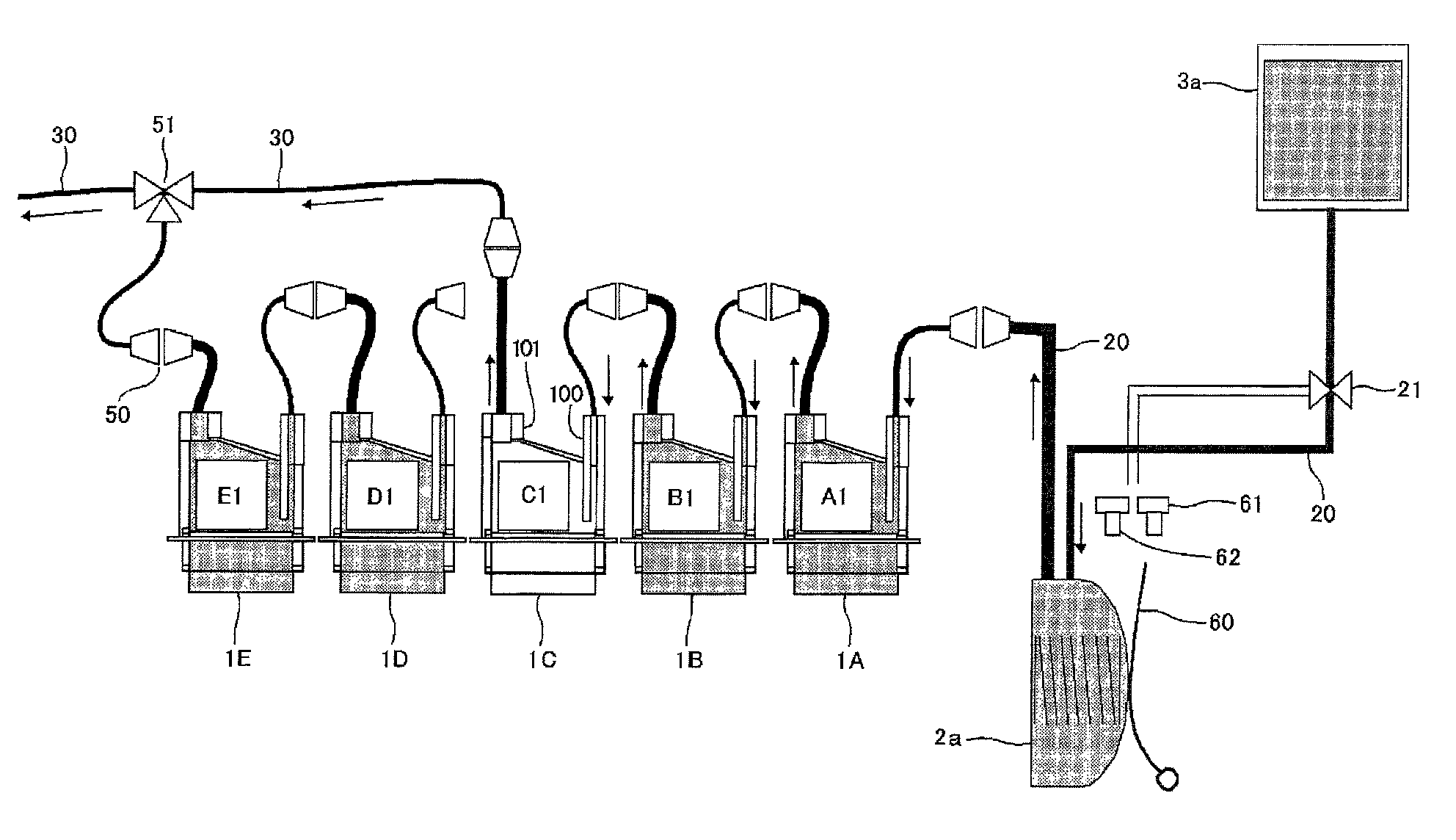
[0112]A supply flow path is connected between adjacent heads and the coupling 50 is installed in the supply flow path in the same manner as in the The coupling 50 can separate (put on and take off) the supply flow path while the ink is loaded in the supply flow path.
[0113]In such a configuration, it suffices to have a smaller number of units of usage of the coupling 50 compared to that in the first embodiment, making it possible to further decrease component costs. Moreover, it may facilitate sending air bubbles into the head tank and discharging the air bubbles from the head tank. Furthermore, at the time of initial loading, air within the sub tank 2a, which is pushed by ink sent from the main tank (the ink cartridge 3a) side, may also be discharged efficiently, making it possible to efficiently discharge air bubbles to the waste liquid flow path 30 via an adjacent head tank.
second embodiment
[0114]FIG. 9 illustrates a connection state at the time of ink loading after head replacement in the ink supply system in the While a case is described here of replacing a center head module (a head module C which includes the head 1C and the head tank C1), the same applies to a case of replacing a different head module.
[0115]In FIG. 9 is shown a state in which a new head module is set at a predetermined position of a line head and ink is not loaded in the head 1C and the head tank C1. When the head module is replaced, the supply port 100 of the head tank C1 is connected to a coupling of the head tank B1 on the upstream side as in an original state, and the discharge port 101 is connected to a coupling 50 which is installed at one end of the waste liquid flow path 30(b). The tri-directional valve 51 is in a state in which the head tank C1 and the waste liquid flow path 30 are open to the atmosphere.
[0116]When loading ink to the head 1C and the head tank C1, in the same manner as th...
third embodiment
[0156]FIG. 23 shows the joint configuration in a front view showing a connection face of the joint on the upstream side and the joint on the downstream side.
[0157]While a joint 270 according to the third embodiment shown is configured to be the same as the joint 170 according to the second embodiment, it is arranged to use two paths (ink flow paths) on an upper step as paths for light color ink and two paths (ink flow paths) on a lower step as paths for dark color ink. In an example shown, paths 72Y and 72C of yellow and cyan are arranged on the upper step as light colors and paths 72K and 72M of black and magenta are arranged on the lower step as dark colors.
[0158]While it is configured for four paths (ink flow paths) to be arranged in a diamond shape or in a staggered fashion in the example shown, it is also possible to apply the third embodiment (with use of an upper step as a path for a light color ink and a lower step as a path for a dark color ink) in a configuration according...
PUM
 Abstract
Description
Claims
Application Information
 - R&D
- Intellectual Property
- Life Sciences
- Materials
- Tech Scout
- Unparalleled Data Quality
- Higher Quality Content
- 60% Fewer Hallucinations
Browse by: Latest US Patents, China's latest patents, Technical Efficacy Thesaurus, Application Domain, Technology Topic, Popular Technical Reports.
© 2025 PatSnap. All rights reserved.Legal|Privacy policy|Modern Slavery Act Transparency Statement|Sitemap|About US| Contact US: help@patsnap.com


