Internal gear pump

a gear pump and internal gear technology, applied in the direction of liquid fuel engines, machines/engines, rotary piston liquid engines, etc., can solve the problems of reducing the efficiency the inability to adjust the height of the teeth when the number of teeth is fixed, and the inability to reduce the size of the internal gear pump, so as to achieve the effect of reducing the size, reducing the height of the teeth, and maintaining the discharging capability of the pump

Active Publication Date: 2014-10-07
JTEKT FLUID POWER SYST CORP +1
View PDF7 Cites 2 Cited by
  • Summary
  • Abstract
  • Description
  • Claims
  • Application Information

AI Technical Summary

Benefits of technology

[0008]The present invention provides an internal gear pump with which both size reduction and improved efficiency can be possible.
[0010]According to this aspect, slippage that occurs between the outer teeth of the inner gear and the inner teeth of the outer gear can appropriately be reduced. In addition, the inner teeth and the outer teeth are formed without using a cycloid curve, and thus height of the teeth is freely adjustable. Therefore, it is possible to achieve size reduction while maintaining a discharging capability of the pump. Furthermore, each of the inner teeth can be arranged in an appropriate position that prevents interference with the adjacent inner teeth.

Problems solved by technology

However, when the cycloid curve is used, height of the teeth cannot be adjusted when the number of teeth is fixed.
If the height of the teeth cannot be freely adjusted, it is impossible to reduce the size of an internal gear pump while maintaining the discharging capability.
It has been known that efficiency of the internal gear pump is reduced by slippage that occurs between the outer tooth of the inner gear and the inner tooth of the outer gear.

Method used


Image

  • Internal gear pump
  • Internal gear pump
  • Internal gear pump

Examples


Embodiment Construction

[0025]A description will hereinafter be made on an embodiment of the present invention with accompanied drawings.

[Overall Structure of an Internal Gear Pump 1 (FIG. 1 to FIG. 3)]

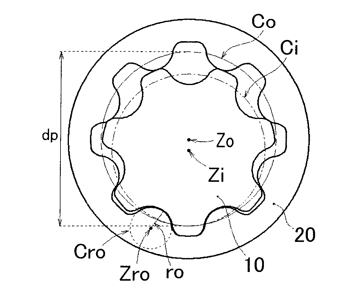
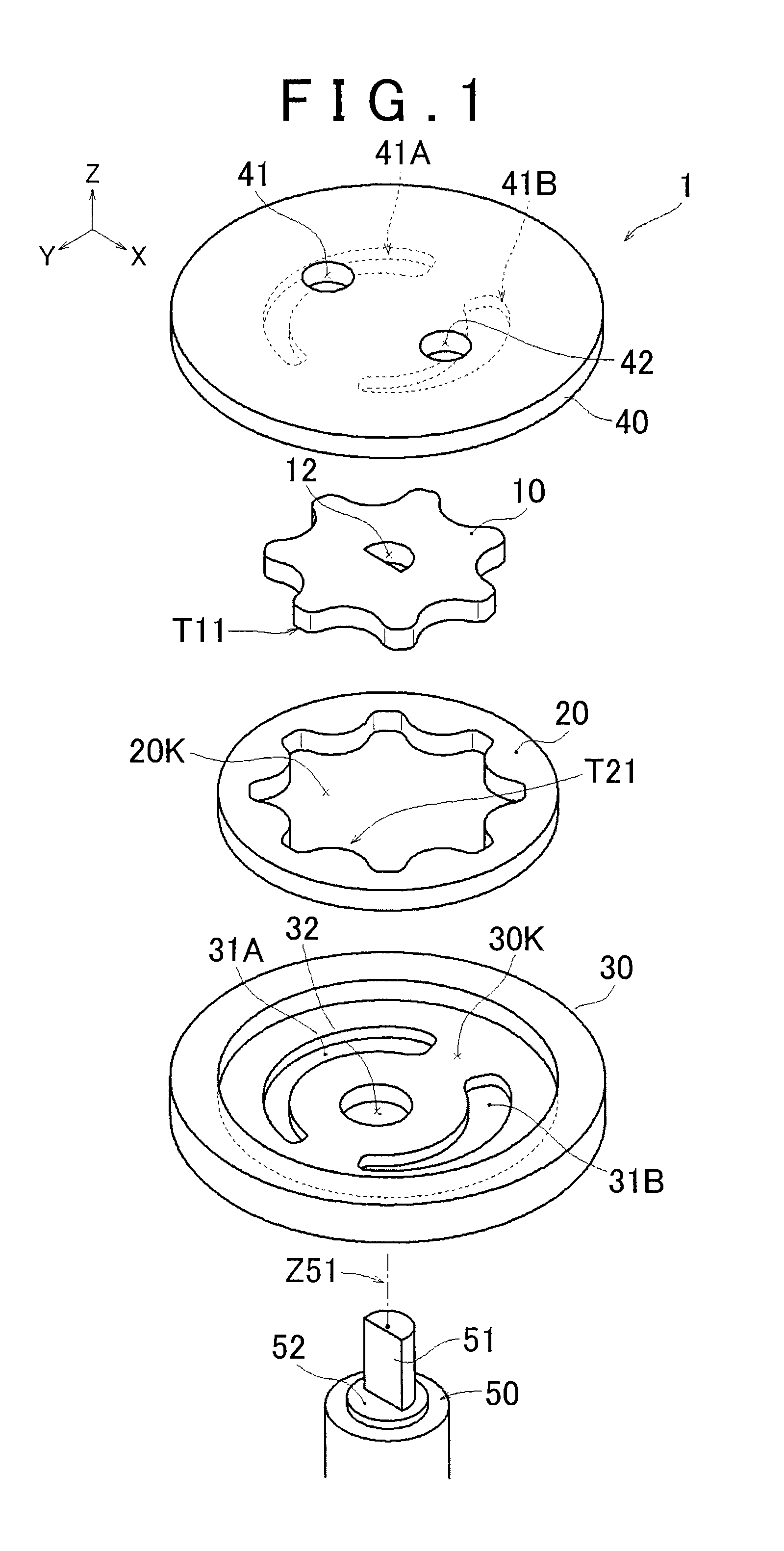
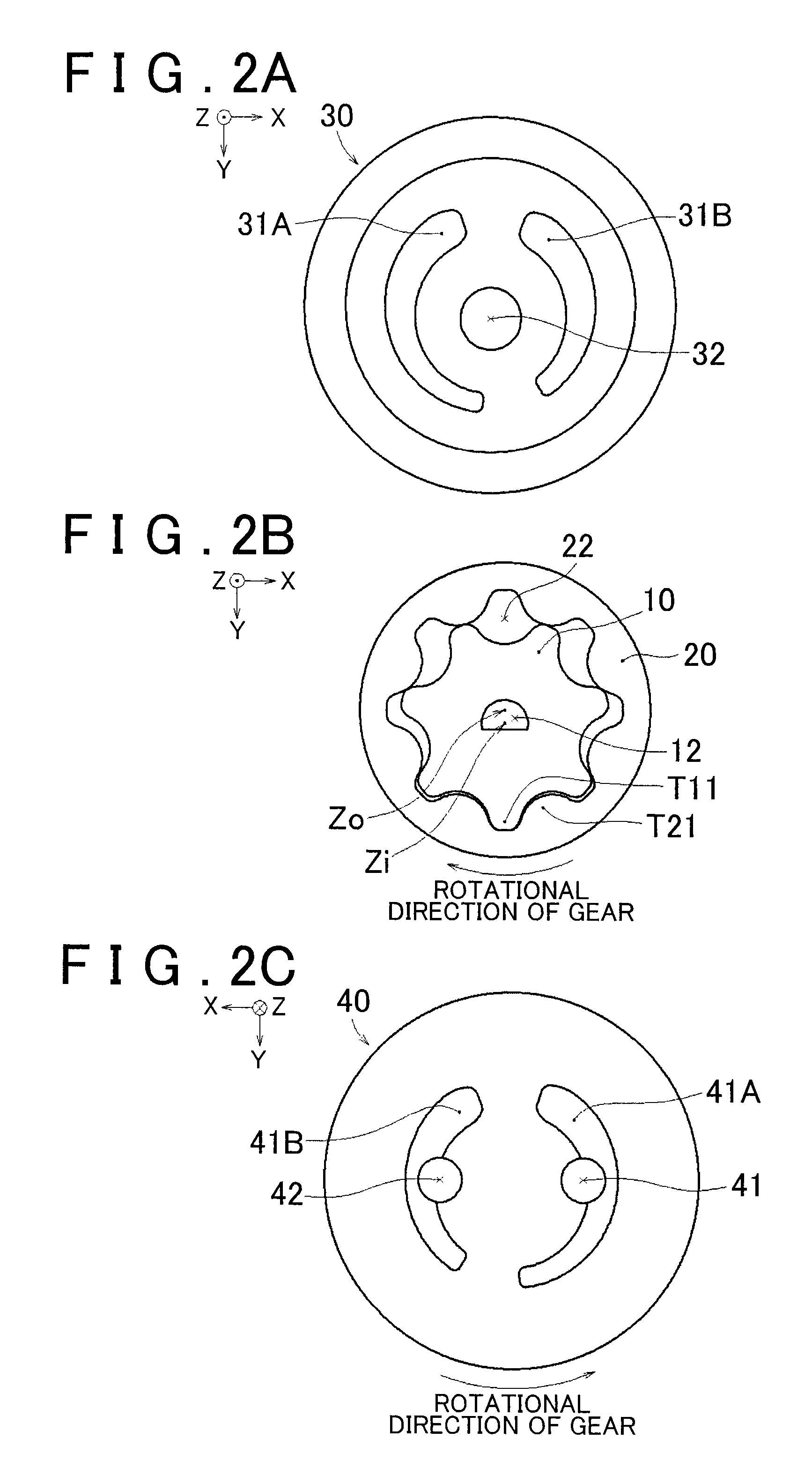
[0026]A description is first made on a structure of an internal gear pump 1 with reference to a perspective view in FIG. 1. The internal gear pump 1 is constructed from an inner gear 10, an outer gear 20, a housing 30, a pump plate 40, and a drive shaft member 50. The inner gear 10 is housed in a housing space 20K of the outer gear 20. The inner gear 10 and the outer gear 20 are housed in a gear housing space 30K that is formed by the pump plate 40, which functions as a rid for the housing 30, and the housing 30. In the drive shaft member 50, a shaft 51, which is rotatable about an axis Z51, is inserted through a through hole 32 formed in the housing 30 and a shaft hole 12 formed in the inner gear 10 so as to drive the inner gear 10 for rotation. This axis Z51 is a rotational axis Zi of the inner gear 10, wh...


PUM


Abstract

In an internal gear pump that includes an inner gear having outer teeth and an outer gear having inner teeth, either the inner or outer teeth have a shape based on a tooth shape that is respectively formed by a generating curve of the outer or inner teeth. The inner teeth are arc-shaped, the outer teeth are curved-shaped, and both end sections of the curved shape are arc-shaped. If a radius of the arc shape of the inner teeth is set as ro, a radius of the arc shape of each of the corner sections is set as ri, a diameter of a pitch circle of the inner teeth is set as dp, and the number of the inner teeth is set as z, the inner gear and the outer gear each has a shape that satisfies a relationship established by following equations: 1.6>ro / (dp / z)>1.0; and ro / (dp / z)>ri / (dp / z)≧0.13. Each of the inner teeth is provided so that an intersecting point between one of arcs that follow the first arc shapes of the adjacent inner teeth and the pitch circle of the inner teeth and in proximity to the other arc is located outside of the other arc.

Description

INCORPORATION BY REFERENCE[0001]The disclosure of Japanese Patent Application No. 2011-267741 filed on Dec. 7, 2011 including the specification, drawings and abstract is incorporated herein by reference in its entirety.BACKGROUND OF THE INVENTION[0002]1. Field of the Invention[0003]The present invention relates to an internal gear pump that performs suction and discharge of fluid by a structure in which an inner tooth of an outer gear meshes with an outer tooth of an inner gear.[0004]2. Description of Related Art[0005]Internal gear pumps have been used such as for automotive oil pumps, and include an inner gear having n outer teeth, an outer gear having n+1 inner teeth that mesh with the outer teeth, and a housing that houses the inner gear and the outer gear therein. The housing is provided with a suction mouth for drawing fluid and a discharge mouth for discharging the fluid. Various shapes have been suggested for the inner teeth of the outer gear and the outer teeth of the inner ...

Claims


Application Information

Patent Timeline
Patent Type & Authority Patents(United States)
IPC IPC(8): F01C1/02F03C2/08F04C2/08F04C2/10
CPCF04C2/103F04C2/102F04C2/084F04C2250/20
Inventor OONO, YOSHIHIROYAMAMORI, MOTOYASUKANDA, DAICHITAKAGI, KENICHI
Owner JTEKT FLUID POWER SYST CORP
Why Eureka
Try Eureka