Variable resonance acoustic transducer

a technology of resonance acoustic transducer and variable resonance, which is applied in the direction of piezoelectric/electrostrictive transducers, transducer types, generators/motors, etc., can solve the problems of inefficiency of the transducer and mismatching of the power amplifier

Active Publication Date: 2014-10-07
UNITED STATES OF AMERICA
View PDF35 Cites 23 Cited by
  • Summary
  • Abstract
  • Description
  • Claims
  • Application Information

AI Technical Summary

Problems solved by technology

These environmental conditions change the resonance frequency of the transducer and cause the transducer to become inefficient and mismatched to its power amplifier.

Method used


Image

  • Variable resonance acoustic transducer
  • Variable resonance acoustic transducer
  • Variable resonance acoustic transducer

Examples


Embodiment Construction

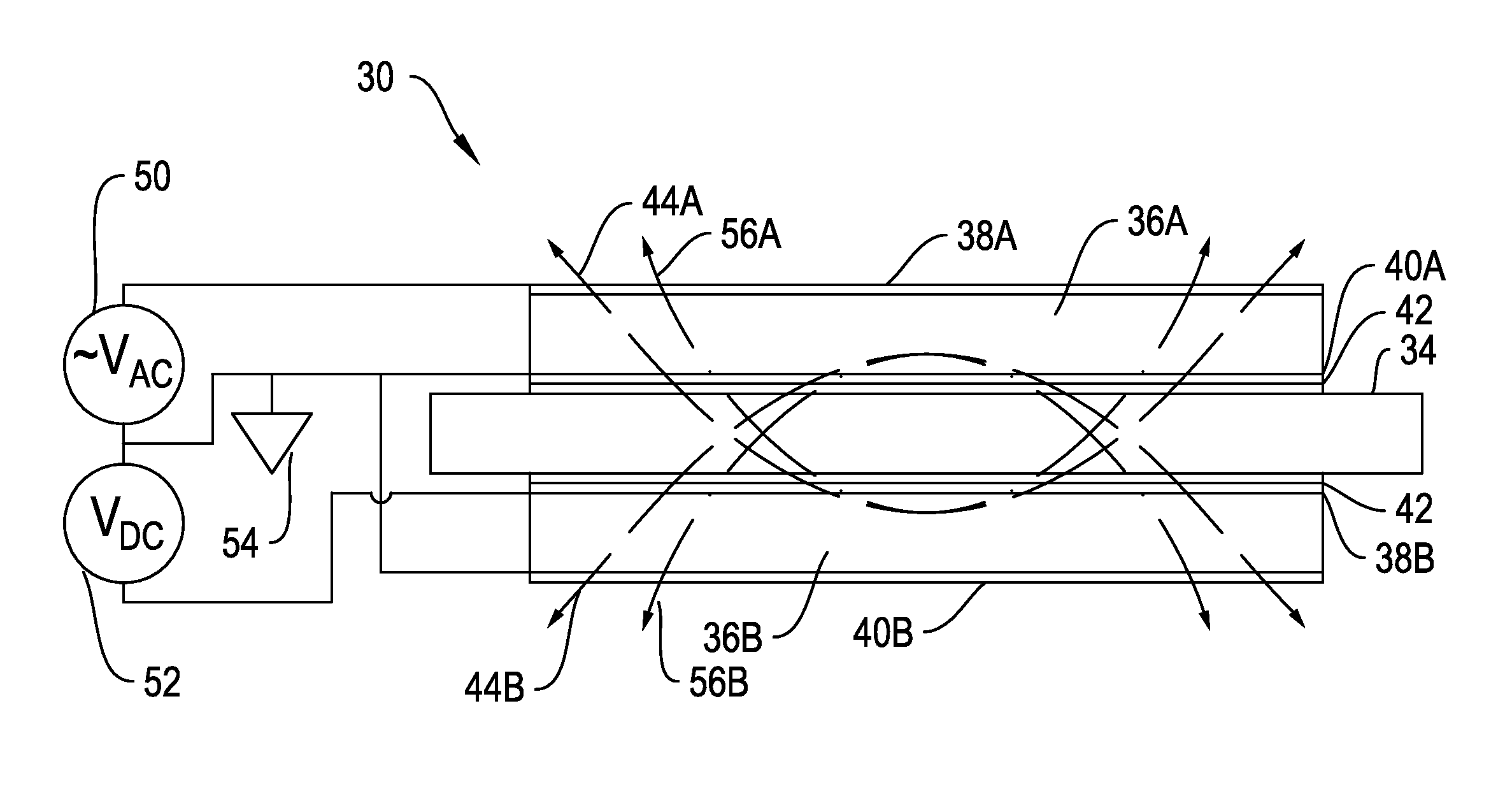
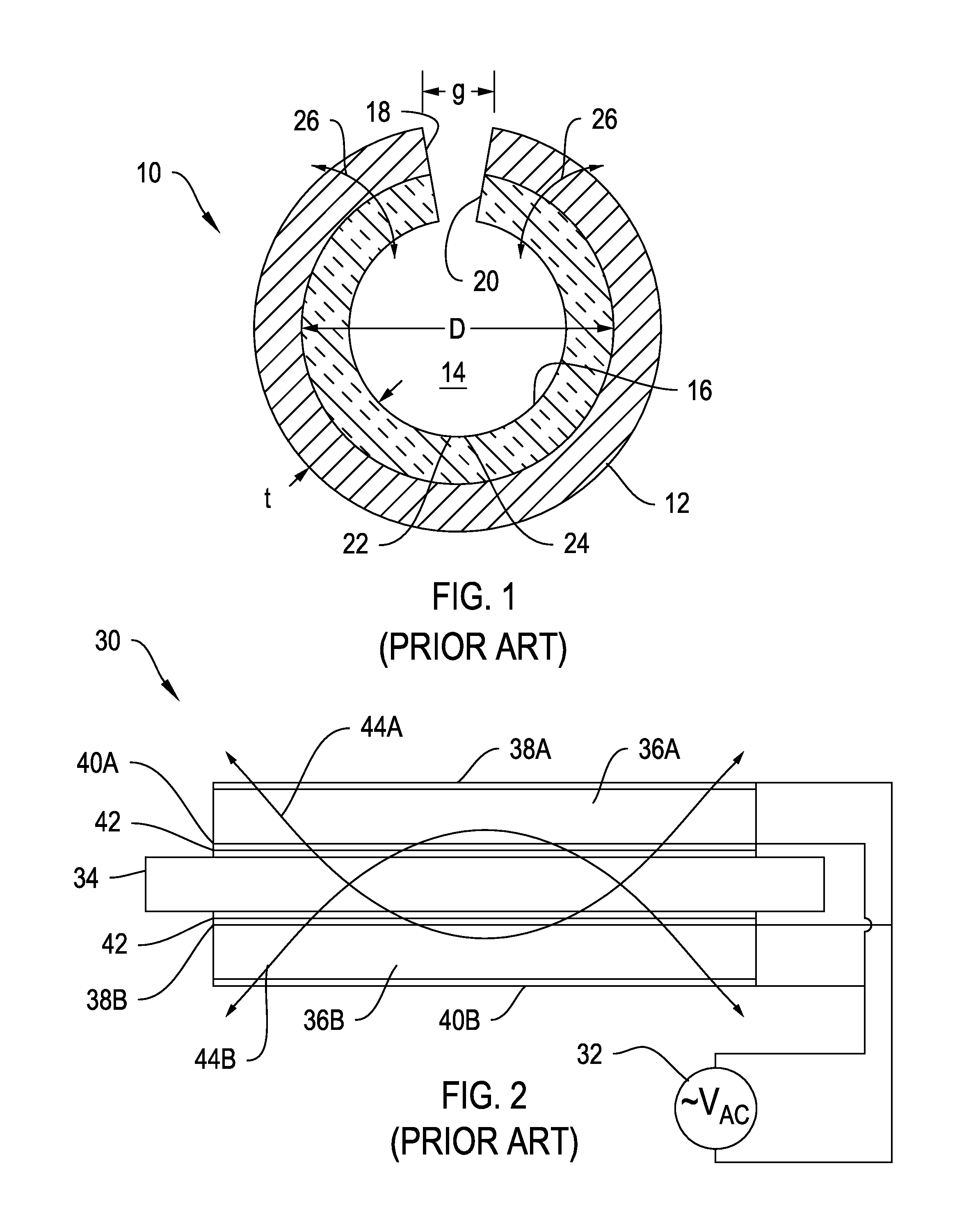
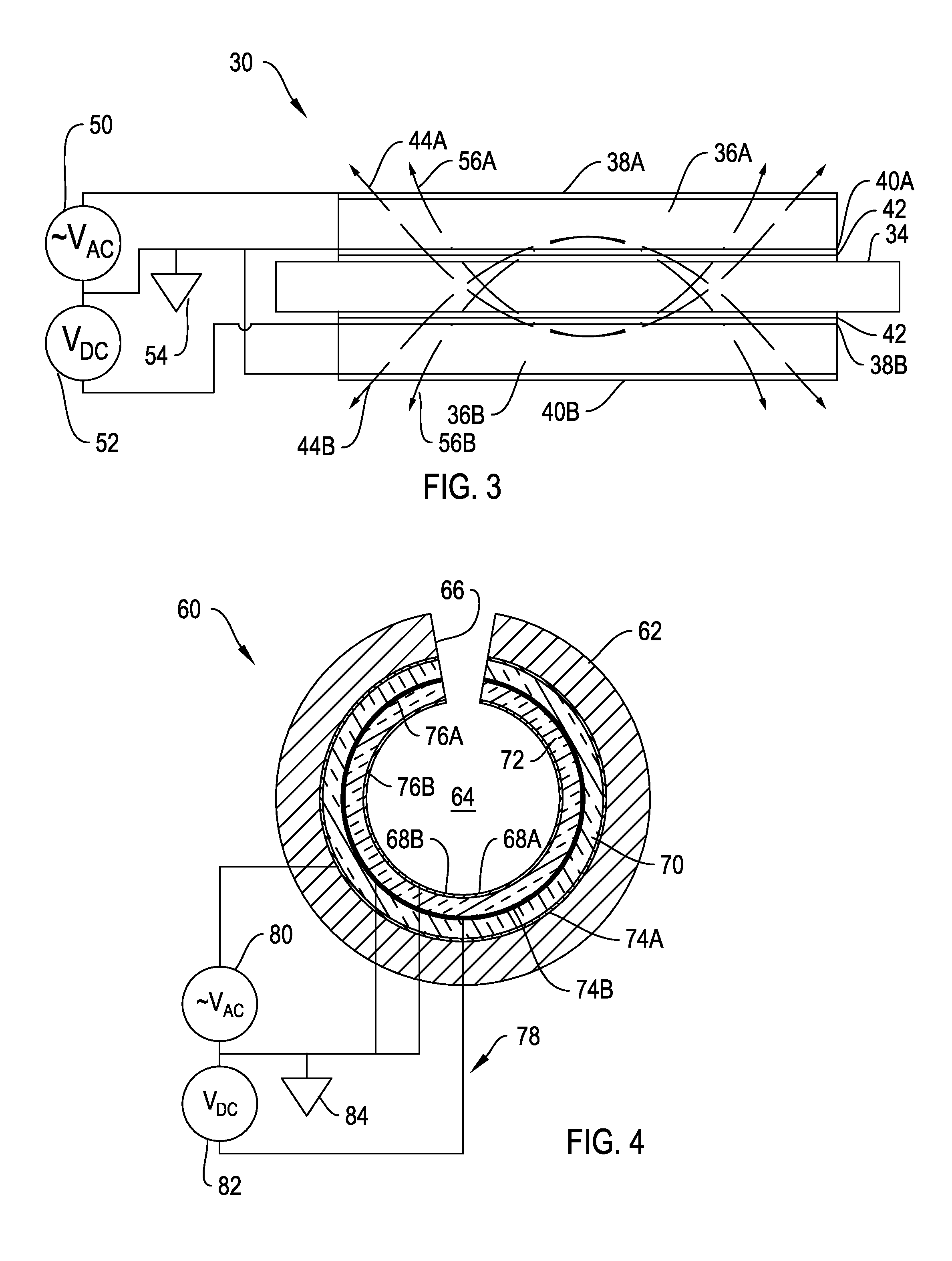
[0023]FIG. 3 shows an embodiment of the current invention as applied to a bender bar 30. The bender bar 30 has a flexible bar 34 joined to transducer member 36A and 36B positioned on either side of bar 34. Electrodes 38A and 38B are positioned in electrical contact on a first side of each transducer member 36A and 36B, and second electrodes 40A and 40B are positioned in electrical contact on a second side of each transducer member 36A and 36B. Insulation 42 is provided to insulate flexible bar 34 from electrodes. Transducer member 36A is poled in the opposite direction from transducer member 36B. This embodiment gives a 3-1 mode of transducer material operation. In this embodiment the transducer members 36A and 36B and flexible bar 34 are operationally the same as used in the prior art.

[0024]Bender bar 30 is joined to a different electrical driver 48 that allows application of a direct current bias to transducer member 36B. Electrical driver 48 has an alternating voltage signal gene...


PUM

PropertyMeasurementUnit
resonance frequencyaaaaaaaaaa
driving voltageaaaaaaaaaa
stiffening voltageaaaaaaaaaa

Abstract

A transducer assembly is provided for projecting acoustic signals into a medium. The assembly includes a support member having first and second layers of piezoelectric material mechanically linked to the support member. The first and second layers are joined to electrical drive circuitry such that one layer receives a driving voltage signal while the other layer receives the driving voltage with a stiffening voltage. The transducer assembly can use both the 3-1 and 3-3 drive modes. Multiple configurations are supported, and both bender bar and slotted cylinder configurations are shown.

Description

STATEMENT OF GOVERNMENT INTEREST[0001]The invention described herein may be manufactured and used by or for the Government of the United States of America for governmental purposes without the payment of any royalties thereon or therefor.CROSS REFERENCE TO OTHER PATENT APPLICATIONS[0002]None.BACKGROUND OF THE INVENTION[0003]1) Field of the Invention[0004]The invention relates generally to increasing the efficiency and frequency band of operation of all transducers / projectors, and particularly slotted cylinder projectors.[0005]2) Description of the Prior Art[0006]It is known to provide slotted cylinder projectors and piezoelectric transducer assemblies. FIG. 1 shows a cross-sectional view of one such prior art transducer. A slotted cylinder transducer 10 features a hollow support member 12 in a cylindrical configuration and having an axial opening 14. The diameter of the support member 12 is D. Transducer material 16 is supported concentrically within the support member and is typica...

Claims


Application Information

Patent Timeline
Patent Type & Authority Patents(United States)
IPC IPC(8): H04R17/00B01B1/06
CPCH04R17/00H04R17/10B01B1/06
Inventor EYSTER, KURT G.
Owner UNITED STATES OF AMERICA
Why Eureka
Try Eureka