Self-contained powered jib boom and optional work platform attachment for mobile cranes

a self-contained, crane-powered technology, applied in the field of jib booms, can solve the problems of not being easily adapted for other use, requiring a lot of labor to attach and detach the jib boom, and the aerial lift articulating boom is not self-contained, so as to achieve safe rotation, easy adjusting, and strong materials

Active Publication Date: 2014-10-14
RAYMOND TIMOTHY JAMES
View PDF18 Cites 22 Cited by
  • Summary
  • Abstract
  • Description
  • Claims
  • Application Information

AI Technical Summary

Benefits of technology

[0004]2. Description of the Related Art
[0005]The mobile crane boom industry has advanced many new crane designs and other product technology over the last 15 years by adding new features and design improvements, such as stronger materials, onboard load-monitoring computers, optional radio remote controls that allow operation of all crane functions from the work platform, load-sensing computerized hydraulic systems, and much more. One area that has not advanced is swing jib booms, and those in use today are basically the same as 40 years ago. A description of what historically has been, and still is, standard for the crane industry regarding removable or pin-on jib booms follows below. Some disadvantages of this prior art are also mentioned below, along with information relating to dedicated work platforms having structure specific to a particular manufacturer or model.
[0006]The standard swing-jib boom currently used with boom truck cranes incorporates a four pin attachment system, which requires a lot of labor to attach and detach the jib boom. The procedural steps for prior art swing-jib boom attachment typically are: 1) Position the crane booms to one side of the truck chassis and deploy downward so that the crane tip sheave head is about 4-feet off ground, making the sheave head easily accessible for the operator to proceed with swing-jib boom attachment. 2) Retract the telescopic booms to allow holes on one side of two steel mounting plates located on the crane boom sheave head tip to line up with complementary holes on steel plates attached to the swing-jib boom while it remains supported by stowage brackets attached to the crane's main outer boom. 3) After aligning holes on the sheave head mounting plates with holes on the steel plates attached to the swing-jib boom, drive two tapered mounting pins through the aligned holes, which will act as a hinge point. 4) Tie a rope to the other (distal) end of the swing-jib boom. 5) Remove the restraints holding the swing-jib boom in place. 6) Raise the crane boom to a level position. 7) Using the rope manually pull the swing-jib boom 180-degrees about the hinge point. 8) Line up the unconnected holes in mounting plates on the crane boom sheave head tip with the remaining unconnected holes in the steel mounting plates attached to the swing-jib boom and drive the two remaining tapered mounting pins into the newly-aligned holes. 9) Remove the pull rope, and the swing-jib boom is now ready for use. In contrast, the present invention jib boom attachment has a hydraulically-powered rotation bearing drive assembly to mechanically rotate the jib boom to any position in a horizontally-extending plane. Thus, when the four tapered mounting pins are connected to the present invention jib boom assembly and the main crane boom sheave head tip, the present invention jib boom attachment can remain at least partially connected to the main crane boom while the hydraulically-powered rotation bearing drive assembly positions it anywhere in a 360-degree rotation range, including the preferred travel position alongside the crane's main boom within road legal width and height requirements.
[0007]The present invention jib boom attachment is also distinguishable from the manufacturer-dedicated jib booms currently in use with mobile crane booms. Mobile crane boom manufacturers do not currently offer, nor are mobile crane booms designed for, a factory-ready (or an after-market) self-contained jib boom that employs, adapts, and / or otherwise incorporates modern aerial lift features with powered rotation and jib boom self-leveling, and any attempt to do so by means other than the self-contained and self-powered jib boom attachment herein would require modification of the entire mobile crane boom assembly to supply the associated work platform with power (hydraulic or electric) for its needed jib boom leveling and rotational features, and would also require a new mechanically-designed platform mounting structure and assembly. Furthermore, for well over twenty years, many aerial lift boom trucks have had articulating booms with work platforms or baskets that allow them to function as aerial man lifts. While these articulating boom aerial lifts have many features and mechanisms that are similar to those of the instant invention, such as powered mechanical articulation and rotation, these aerial lifts are also designed and manufactured with many dedicated / integral components that work only with their own specifically designed product, and cannot be easily adapted for other use, such as being an after-market attachment to a mobile crane or boom truck crane. Furthermore, such aerial lift articulating booms are not self-contained, and power from the associated truck is needed for its work platform leveling and rotation functions. Thus, such prior art articulating booms are not designed to function as an after-market add-on jib boom and work platform attachment, as is the present invention, instead being an original and dedicated integral component of its associated aerial lift boom truck. In addition, these aerial lift boom trucks do not have a swing-jib or a boom tip designed sheave head configured for a swing-jib, and thus do not secure their booms or platforms in position using a standard swing-jib pinning system. Instead, they are all designed to be connected to attachment points specifically designed for support of their individual work platforms. Furthermore, in prior art and current aerial lift boom trucks, hydraulic or electrical power for work platform leveling and rotation is typically supplied from the ground by the supporting vehicle, an auxiliary engine, or a large battery-powered power unit, via hose / cable carriers or retractable reels attached to the boom assemblies, none of which are required during use of the self-contained self-powered present invention embodiments.
[0008]Thus, in contrast to the prior art, the present invention comprises the following features and advantages which make it structurally distinguishable. Leveling of the present invention jib boom with or without a work platform is accomplished by means of an onboard mechanically-powered automatic hydraulic / electronic leveling system that senses an out-of-level state in the jib boom or its attached work platform, and then operates a hydraulic leveling cylinder to articulate the jib boom with or without a work platform level while the crane boom is raised or lowered, regardless of the position of the work platform, onboard personnel, or its payload. When the crane boom is stopped, the jib boom's leveling cylinder employs several holding valves that lock the work platform into a level orientation. Thus, a loaded present invention jib boom can be safely rotated in the horizontal plane while it is in the locked position, and its load, including personnel, are also safe as a result of its powered-leveling while the boom is being raised or lowered. Also, in addition to powered-leveling, rotation will now be available on mobile cranes due to other integral design features of the present invention, including its strong rotational drive bearing assembly, a torsion-resistant tubular jib boom support structure, and a rigid and strong planar mounting bracket that anchors the present invention jib boom to the strong structural swing-jib sheave head while transferring all torsion and bending moments induced by off-set jib boom loads to the main crane boom's swing-jib sheave head.
[0009]In contrast to the current prior art mobile crane jib booms which lack any form of rotation, the present invention jib boom with or without an attached work platform advantageously incorporates a hydraulic-powered rotation bearing drive assembly that allows it to rotate in a 360-degree horizontal plane, with the present invention jib boom and an attached work platform being maintained automatically in a level state (or locked into a level orientation) during all of its 360-degree rotation range, and as the attached main crane boom is raised or lowered. Also, optionally, after the main crane boom stops vertical articulation, the level orientation of the present invention jib boom and an attached work platform can be locked during subsequent rotation with stops in its linear leveling actuator. Furthermore, the total power supply, mechanical actuation, and function controls in the self-contained most preferred embodiments of the present invention are all encompassed in a self-contained 12-volt battery-powered power pack integral with its jib boom assembly, thus eliminating the need for connecting hoses or power cables alongside the booms or an attached work platform, as well as eliminating the need for hose reels or cable carriers, unless applications dictate otherwise. In addition, a shear ball bearing and hydraulic gear drive mechanism in the present invention allows a dielectric-rated insulated jib boom and attached work platform to be used much like that of an aerial lift boom truck for working on live power lines. The universal-style mounting design of the present invention also allows it to be mounted to most commercial crane boom ends having a swing-jib mounting system, as the present invention is configured to use the swing-jib anchor points that most cranes now incorporate as a standard feature. As mentioned hereinabove, the prior art swing-jib mounting system allows for a simple four pin connection of the present invention jib boom and attached work platform to a main crane boom tip. In addition, the mechanically-powered leveling feature of the present invention jib boom allows for road-ready-stowed travel while at least partially attached to the main crane boom sheave head tip, enabling the attached jib boom to be rotated outboard into a substantially parallel position alongside a main crane boom within road-legal width and height requirements, while concurrently clearing the cab chassis roof and driver's vision, thus allowing the present invention jib boom with or without an attached work platform to remain connected to the main crane's boom tip during road travel to a next work site, saving significant set-up time at the next work location after the crane's outriggers are set.

Problems solved by technology

The standard swing-jib boom currently used with boom truck cranes incorporates a four pin attachment system, which requires a lot of labor to attach and detach the jib boom.
Mobile crane boom manufacturers do not currently offer, nor are mobile crane booms designed for, a factory-ready (or an after-market) self-contained jib boom that employs, adapts, and / or otherwise incorporates modern aerial lift features with powered rotation and jib boom self-leveling, and any attempt to do so by means other than the self-contained and self-powered jib boom attachment herein would require modification of the entire mobile crane boom assembly to supply the associated work platform with power (hydraulic or electric) for its needed jib boom leveling and rotational features, and would also require a new mechanically-designed platform mounting structure and assembly.
While these articulating boom aerial lifts have many features and mechanisms that are similar to those of the instant invention, such as powered mechanical articulation and rotation, these aerial lifts are also designed and manufactured with many dedicated / integral components that work only with their own specifically designed product, and cannot be easily adapted for other use, such as being an after-market attachment to a mobile crane or boom truck crane.
Furthermore, such aerial lift articulating booms are not self-contained, and power from the associated truck is needed for its work platform leveling and rotation functions.
In addition, these aerial lift boom trucks do not have a swing-jib or a boom tip designed sheave head configured for a swing-jib, and thus do not secure their booms or platforms in position using a standard swing-jib pinning system.
In 1983, when the Griffiths patent application was filed, others were making and using electronic leveling sensors on work baskets / platforms, such as those available from P-Q Controls in Bristol, Conn., but these baskets / platforms did not have onboard battery power.

Method used


Image

  • Self-contained powered jib boom and optional work platform attachment for mobile cranes
  • Self-contained powered jib boom and optional work platform attachment for mobile cranes
  • Self-contained powered jib boom and optional work platform attachment for mobile cranes

Examples


Embodiment Construction

[0043]The description herein provides preferred embodiments of the present invention but should not be construed as limiting its scope. Instead, the scope of the present invention should be determined by the appended claims and their legal equivalents, rather than being limited to the examples given.

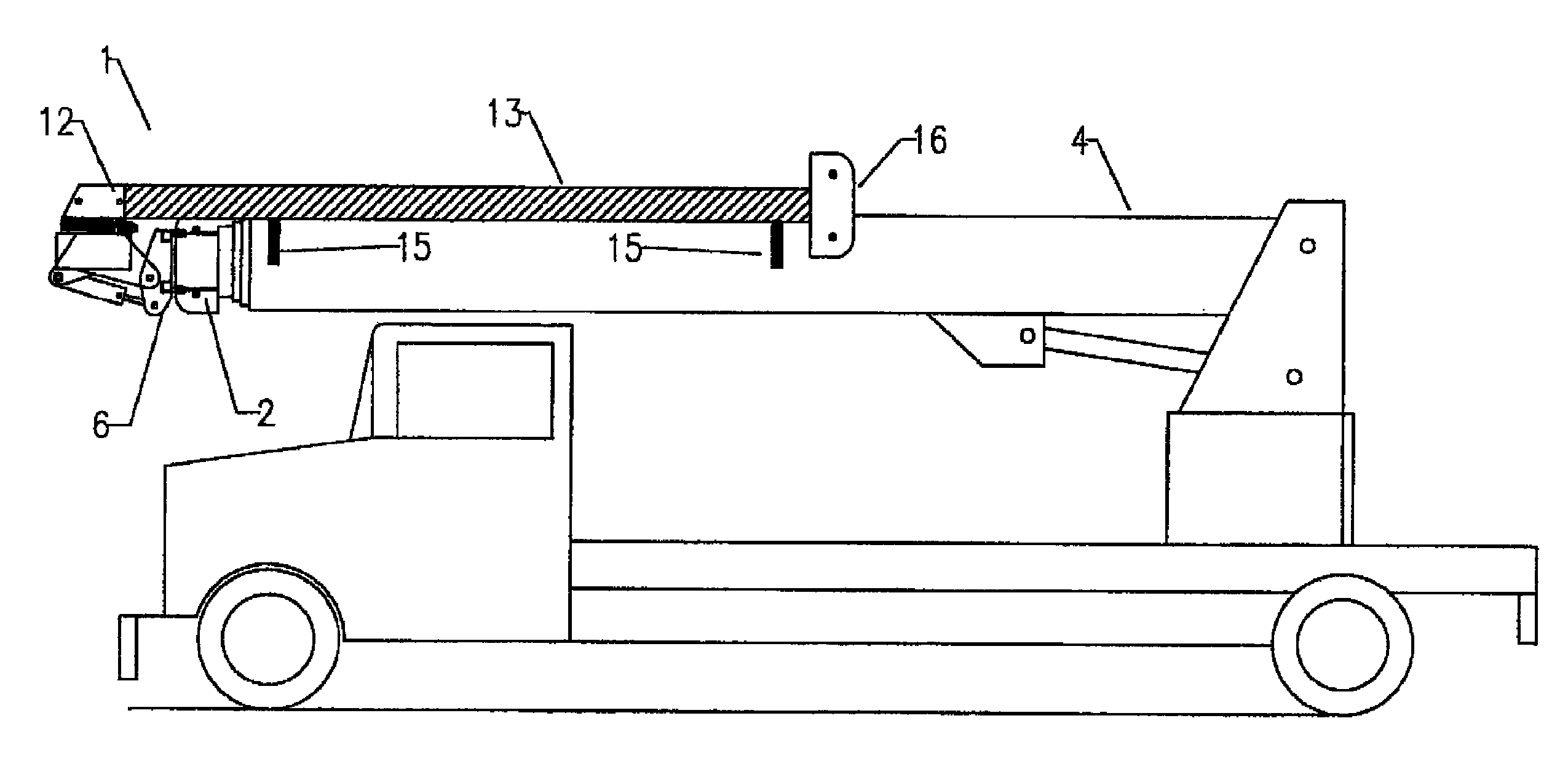
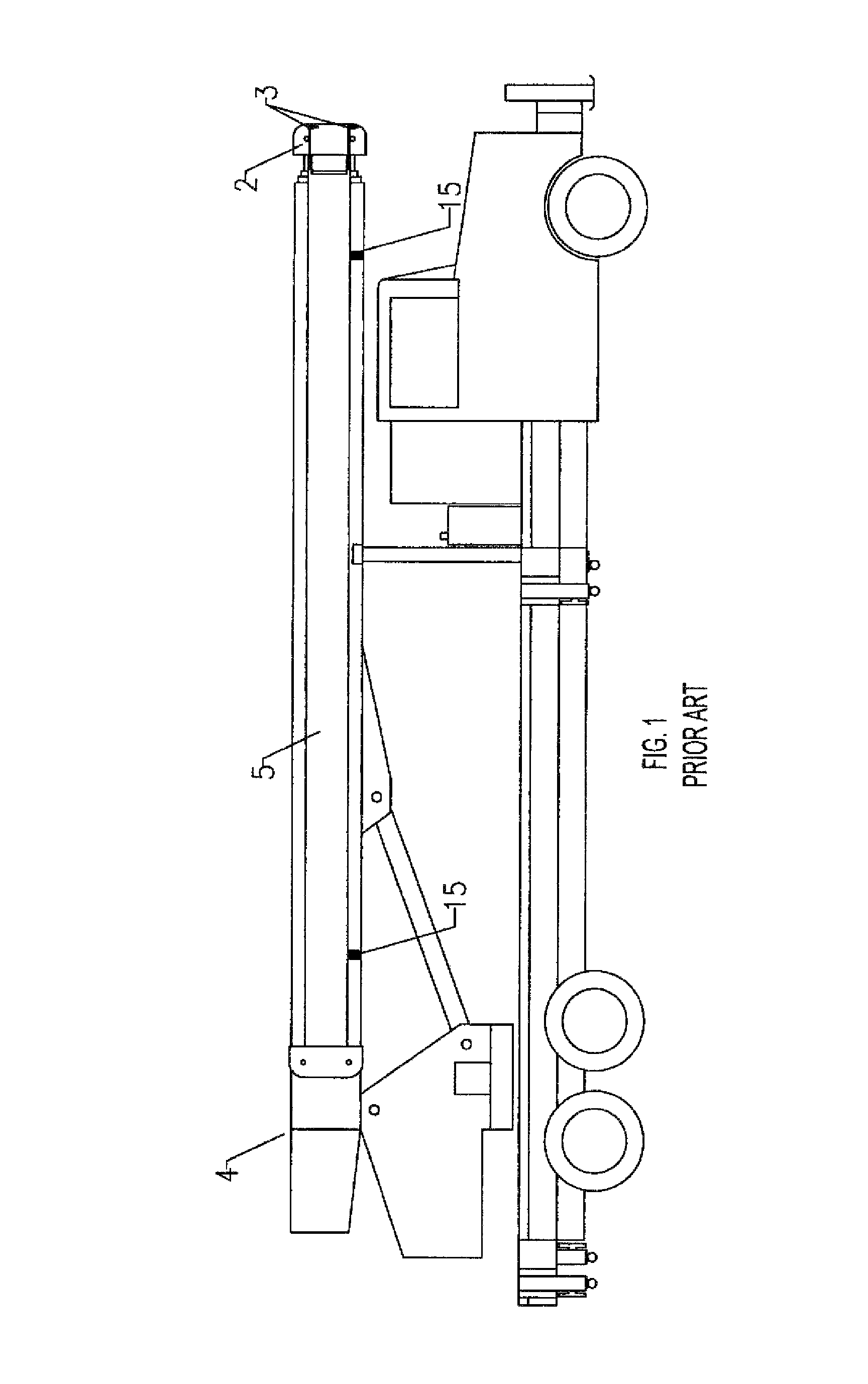
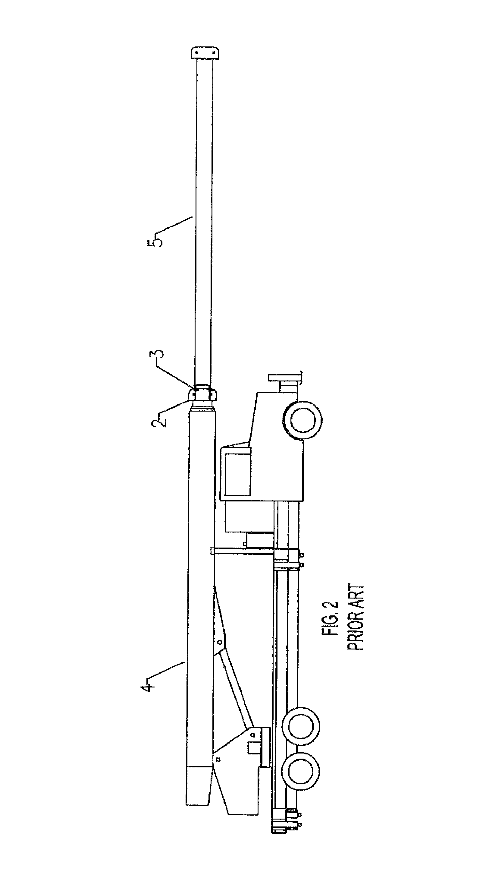
[0044]This invention provides a universal and ready-to-use self-contained jib boom attachment 1 (including at a minimum jib boom tube 13, jib boom support structure 12, jib boom mounting bracket 6, and optional work platform 14) that is primarily intended for use with mobile and boom truck cranes, such as but not limited to those shown in FIGS. 1 and 19, which enables use of jib boom tube 13 as an articulating and rotating extension of the crane's main boom 4 for easy movement of jib boom tube 13 and optional work platform 14 around objects and obstacles confronted in aerial work sites, to provide better access of onboard personnel to many parts of the elevated work site without having t...


PUM


Abstract

A powered rotating and articulating self-contained jib boom of both swing jib and non-swing jib design that attaches to mobile cranes and functions as an aerial lift when fitted with an optional work platform. Since it pins onto any existing crane by attachment to a standard swing-jib mounting system using the four pinning holes and pins located on the crane's outer most boom tip sheave head, it achieves powered leveling and rotation of a platform without having to modify or add components to the existing crane. Also, with the crane jib boom hydraulically powered for rotation in the horizontal plane up to 360-degrees and articulation in a 90-degree vertical plane, an attached work platform can be kept level during up/down articulation of the crane boom in its vertical plane. Furthermore, with dielectric insulation, the jib boom, crane boom, and attached work platform are usable on live electrical line work.

Description

CROSS-REFERENCES TO RELATED APPLICATIONS[0001]The applicant herein requests domestic priority for the instant application based upon his earlier filed U.S. provisional patent application for similar subject matter, which has a title of “Crane attachment insulated aerial lift jib boom with platform”, a U.S. provisional application number of 61 / 689,801, and a filing date of Jun. 14, 2012.BACKGROUND[0002]1. Field of the Invention[0003]This invention relates to jib booms used with cranes and telescopic boom assemblies, particularly to a hydraulically powered jib boom (of both swing jib and non-swing jib design) with an optional self-contained work platform attachment having auto-powered leveling and 360-degree rotation that can be used with mobile cranes and boom truck cranes, wherein when such mobile and boom truck cranes include a swing-jib mounting system, the invention can be mounted to the standard crane tip swing-jib mounting plates already incorporated thereon, advantageously usi...

Claims


Application Information

Patent Timeline
Patent Type & Authority Patents(United States)
IPC IPC(8): B66F11/04
CPCB66F11/046B66C23/702
Inventor RAYMOND, TIMOTHY, JAMES
Owner RAYMOND TIMOTHY JAMES
Why Eureka
Try Eureka