Control apparatus

a control apparatus and control technology, applied in the field of control apparatus, can solve the problem of not being able to meet the restraint condition such as the identification of model parameters, and achieve the effects of improving control accuracy and stability, accurate identification of model parameters, and improving the accuracy of identification of model parameters

Active Publication Date: 2014-10-14
HONDA MOTOR CO LTD
View PDF20 Cites 40 Cited by
  • Summary
  • Abstract
  • Description
  • Claims
  • Application Information

AI Technical Summary

Benefits of technology

[0036]With the configuration of the preferred embodiment, in a case where the control target model of the controlled object having the first or higher order lag characteristic includes the N model parameters, it is possible to obtain the same advantageous effects as described above. More specifically, even when the lag characteristic of the controlled object changes along with changes in the reference parameter, it is possible to identify the N model parameters while causing such changes in the lag characteristic to be reflected on the model parameters. In addition to this, since the M weight function values are set as mentioned above, even when the lag characteristic suddenly changes along with a sudden change in the reference parameter, it is possible to identify the N model parameters such that they change steplessly and smoothly while properly compensating for the sudden change in the lag characteristic. For the above reason, even when the controlled object is in a transient condition, it is possible to accurately identify the N model parameters. As a result, it is possible to further improve the control accuracy and stability.
[0037]To attain the above object, in a third aspect of the present invention, there is provided a control apparatus for controlling a controlled variable of a controlled object having a first or higher order lag characteristic, by a control input, comprising first reference parameter-detecting means for detecting a first reference parameter which influences the lag characteristic, second reference parameter-detecting means for detecting a second reference parameter which influences the lag characteristic, reference model parameter-calculating means for calculating, according to the detected first reference parameter, a reference model parameter as a reference value of a model parameter of the control target model, weight function value-calculating means for calculating, according to the detected second reference parameter, M weight function values (M represents an integer not smaller than 2) associated with the second reference parameter, estimated controlled variable-calculating means for calculating an estimated controlled variable which is an estimated value of the controlled variable using a control target model of a discrete-time system defining a relationship between the controlled variable and the control input of the controlled object, error-calculating means for calculating an error between the calculated estimated controlled variable and the controlled variable, range identification error-calculating means for calculating M first products by multiplying the calculated error by the calculated M weight function values, and calculating M range identification errors using the M first products, modification value-calculating means for calculating M modification values such that the calculated M range identification errors are each minimized, identification means for calculating M second products by multiplying the M calculated modification values by the M weight function values, respectively, and identifying onboard the model parameter by adding a total sum of the M second products to the calculated reference model parameter, and control input-calculating means for calculating the control input using the identified model parameter and a control algorithm derived based on the control target model, wherein the M weight function values are associated with M ranges of the first reference parameter, respectively, the M weight function values each being set to values other than 0 in an associated range and set to 0 in ranges other than the associated range, and adjacent ones of the M ranges overlap each other.
[0038]With the configuration of this control apparatus, the controlled object has the first or higher order lag characteristic as the dynamic characteristic, and the reference model parameter is calculated as the reference value of the model parameters of the control target model according to the first reference parameter which influences the lag characteristic. Further, the M weight function values associated with the second reference parameter are calculated according to the second reference parameter which influences the lag characteristic. Further, the estimated controlled variable as an estimated value of the controlled variable is calculated using the control target model of the discrete-time system defining the relationship between the controlled variable of the controlled object and the control input, and the M first products are calculated by multiplying the error between the calculated estimated controlled variable and the controlled variable by the M weight function values. The M range identification errors are calculated using the M first products. Further, the M modification values are calculated such that the M range identification errors are each minimized, and the M second products are calculated by multiplying the M modification values by the M weight function values, respectively. The model parameters are identified onboard by adding the total sum of the M second products to the reference model parameter.
[0039]The model parameters are identified as described above, even when the lag characteristic changes along with changes in the first reference parameter and / or the second reference parameter, it is possible to identify the model parameters while causing such changes in the lag characteristic to be reflected on the model parameters. In addition to this, the M weight function values are associated with M ranges of the reference parameter, respectively, and are each set to a value other than 0 in the associated range, and set to 0 in ranges other than the associated range. Further, the adjacent ones of the M ranges overlap each other. Therefore, even when the lag characteristic suddenly changes along with a sudden change in the reference parameter, it is possible to identify the model parameters such that they change steplessly and smoothly while properly compensating for the sudden change in the lag characteristic. For the above reason, even when the controlled object is in a transient condition, it is possible to accurately identify the model parameters.
[0040]Further, the M modification values are calculated such that the M range identification errors are each minimized, and the model parameters are identified by adding the total sum of the M second products obtained by multiplying the calculated M modification values by the M weight function values, respectively to the reference model parameter. Therefore, the reference model parameter is used as an initial value at a time when the identification computation is started, and since the reference model parameter is calculated according to the first reference parameter which influences the lag characteristic, even immediately after the start of computation for identifying the model parameters, it is possible to identify the model parameters while causing the lag characteristic of the controlled object to be reflected on the model parameters, whereby it is possible to further improve the accuracy of identification of the model parameters. From the above, it is possible to further improve the control accuracy and stability.
[0041]In the third aspect of the present invention, preferably, the control target model includes N model parameters (N represents an integer not smaller than 2), the reference model parameter-calculating means calculates a reference model parameter vector which is composed of N reference model parameters as elements, which are reference values of the N model parameters, the range identification error-calculating means calculates M range identification error vectors each composed of N values as elements, as the M range identification errors, the modification value-calculating means calculates M modification value vectors each composed of N values as elements, as the M modification values, the identification means calculates M second product vectors each composed of N values as elements, as the M second products, by multiplying the M modification value vectors by the M weight function values, respectively, and identifies onboard a model parameter vector which is composed of the N model parameters as elements, by adding a total sum of the M second product vectors to the reference model parameter vector, and the control input-calculating means calculates the control input using the identified model parameter vector and the control algorithm.

Problems solved by technology

Therefore, as described hereinabove, if a general identification algorithm, such as the sequential least-squares method, is used, it is impossible to identify the model parameters such that the restraint condition is satisfied.

Method used


Image

  • Control apparatus
  • Control apparatus
  • Control apparatus

Examples


first embodiment

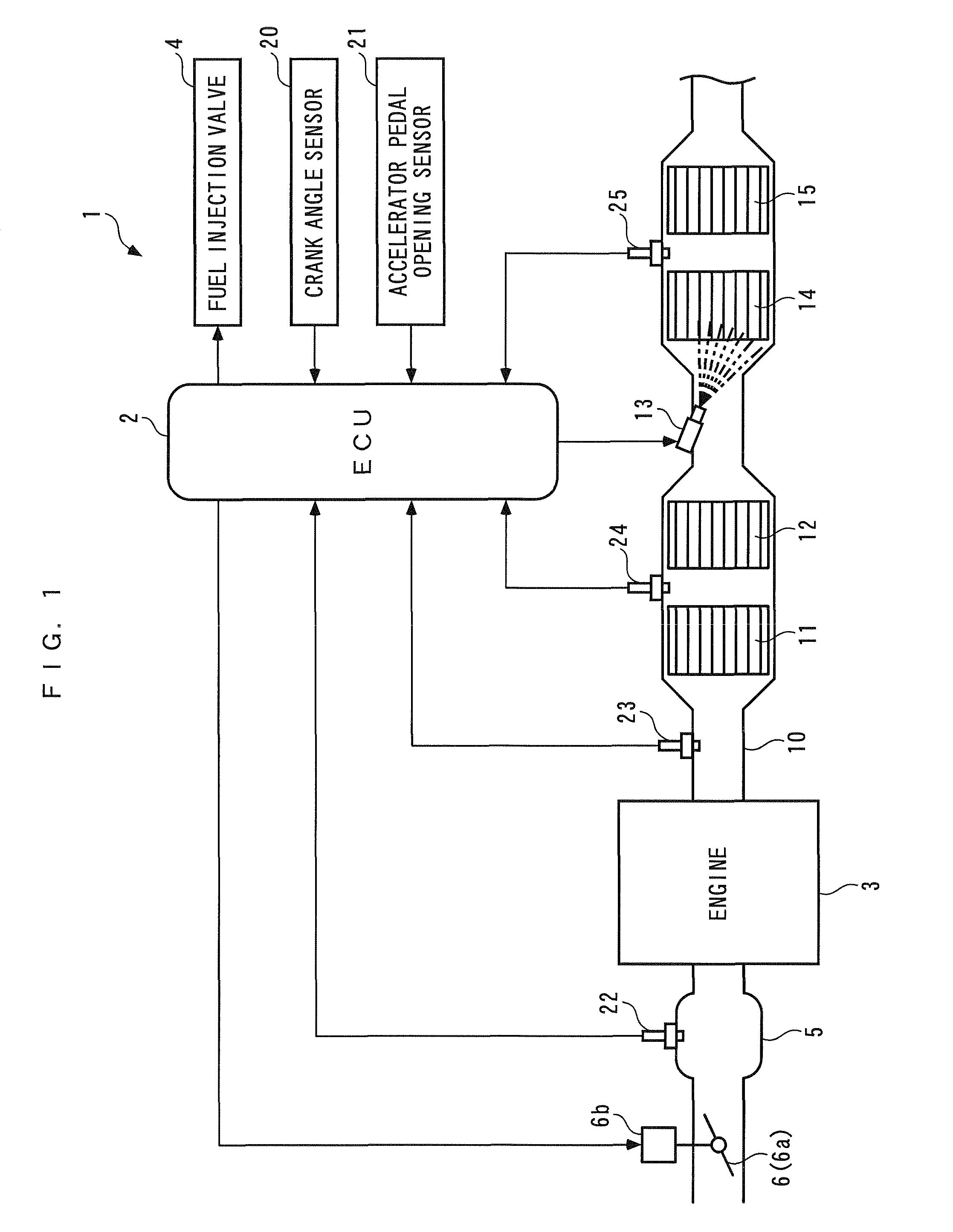
[0105]Hereafter, a control apparatus according to the invention will be described with reference to drawings. The control apparatus according to the present embodiment, denoted by reference numeral 1 as illustrated in FIG. 1, controls the air-fuel ratio of an air-fuel mixture supplied to an internal combustion engine (hereinafter simply referred to as the “engine”) 3, and includes an ECU 2.

[0106]The engine 3 is a direct injection gasoline engine installed on a vehicle, not shown, and includes fuel injection valves 4 (only one of which is shown) provided for respective cylinders. Each fuel injection valve 4 is electrically connected to the ECU 2, and a valve-opening time period and a valve-opening timing thereof are controlled by the ECU 2, whereby fuel injection control is performed. In this case, under normal operating conditions, the fuel injection control is executed such that the air-fuel ratio of the air-fuel mixture is controlled to a leaner value than the stoichiometric air-f...

second embodiment

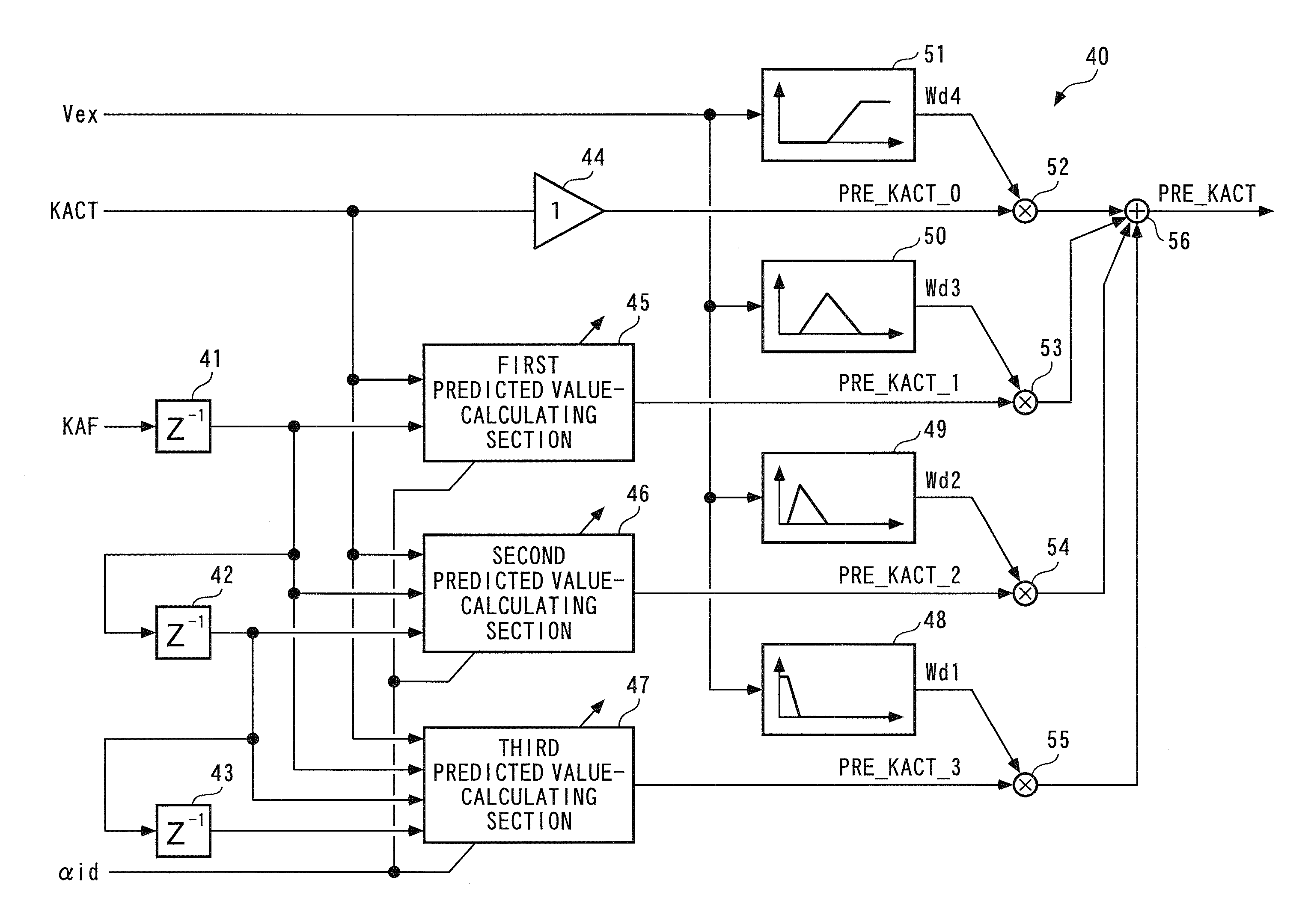
[0379]According to the control apparatus 1A of the second embodiment, configured as described above, the onboard identifier 260 identifies the model parameter vector θ, i.e. the two model parameters δ and α with the identification algorithm expressed by the equations (74) to (86), as described above. In this case, the model parameter vector θ is calculated by adding the total sum of the products Wai·dθi of the four weight function values Wai (i=1 to 4) and the four modification term vectors dθi to the reference model parameter vector θbs, so that the reference model parameter vector θbs is used as an initial value of the model parameter vector θ at a time when the identification computation is started. In addition to this, the reference model parameter αbs is calculated by searching the FIG. 10 map according to the exhaust gas volume Vex having a high correlation with the first-order lag characteristic between the air-fuel ratio correction coefficient KAF and the detected equivalent...

fifth embodiment

[0499]As described hereinabove, according to the control apparatus 1D of the fifth embodiment, the onboard identifier 530 calculates the identified value αid″ of the model parameter α″ with the aforementioned identification algorithm expressed by the equations (112) to (124) using the equation (105) as the control target model. In this case, the identification algorithm expressed by the equations (112) to (124) is derived by the same method as the method used for deriving the identification algorithm for the above-described onboard identifier 60, and hence it is possible to accurately calculate the identified value αid″ of the model parameter α″ while satisfying the restraint condition between the two model parameters α″ and 1−α″ in the equation (105). Further, the control input Uact is calculated using the identified value αid″ identified as above, and hence it is possible to prevent a modeling error due to changes in the first-order lag characteristic caused by changes in the oil ...


PUM


Abstract

A control apparatus capable of improving the control accuracy and stability when controlling a controlled object with a predetermined restraint condition between a plurality of model parameters, or a controlled object having a lag characteristic, using a control target model of a discrete-time system. The control apparatus has an ECU which arranges a control target model including two model parameters such that terms not multiplied by the model parameters and terms multiplied by the same are on different sides of the model, respectively. Assuming the different sides represent a combined signal value and an estimated combined signal value, respectively, the ECU calculates onboard identified values of the model parameters such that an identification error between the signal values is minimized, and calculates an air-fuel ratio correction coefficient using the identified values and a control algorithm derived from the control target model.

Description

FIELD OF THE INVENTION[0001]The present invention relates to a control apparatus for controlling a controlled object having a lag characteristic, such as a first-order lag characteristic, using a control target model of a discrete-time system.DESCRIPTION OF THE RELATED ART[0002]Conventionally, the present assignee has already proposed a control apparatus disclosed in Japanese Laid-Open Patent Publication (Kokai) No. 2000-234550 as a control apparatus for controlling the air-fuel ratio of an air-fuel mixture supplied to an internal combustion engine. The control apparatus includes a LAF sensor, an oxygen concentration sensor, a state predictor, an onboard identifier, a sliding mode controller, a target air-fuel ratio-calculating section, and so forth. Both the LAF sensor and the oxygen concentration sensor detect a value indicative of the concentration of oxygen in exhaust gases, i.e. an air-furl ratio, in an exhaust passage of the engine and are provided in the exhaust passage at lo...

Claims


Application Information

Patent Timeline
Patent Type & Authority Patents(United States)
IPC IPC(8): G05B13/02G05B11/01G06F19/00G06F17/00G06F7/00B60W10/10B60W10/04
CPCG05B13/042G05B2219/25298Y10T477/675Y10T477/679
Inventor YASUI, YUJI
Owner HONDA MOTOR CO LTD
Why Eureka
Try Eureka