Electric power distribution system

a technology of power distribution system and power distribution system, which is applied in non-electric variable control, process and machine control, instruments, etc., can solve the problems of not being able to establish a basic solution for facilitating the effective use of power, and the mechanism of such a solution has not yet been established

Inactive Publication Date: 2014-10-14
PANASONIC CORP
View PDF36 Cites 16 Cited by
  • Summary
  • Abstract
  • Description
  • Claims
  • Application Information

AI Technical Summary

Benefits of technology

[0012]In accordance with the above configuration, when network communication using the Internet as a medium is employed as the communication means, network communications having high generality can be implemented and the range of application thereof can be extended in the case where the amount of power consumption and the amount of surplus power of each supply destination are collected in the management server by the remote electricity monitoring device.
[0042]In general, under a pole transformer, five to ten dwellings or the like are present as power supply destinations, so that dwellings supplied with power from this pole transformer are called a minimum group for power distribution. Accordingly, micro-power distribution can be performed among the five to ten dwellings as each unit that is supplied with power from the pole transformer, and power transmission loss is suitably reduced upon efficiently supplying power to each supply destination. Further, when the sub-management server is installed on the pole transformer in this way, management is facilitated in the case where the supply of power to each dwelling and both the power consumption amount information and the surplus power amount information are managed by the sub-management server.

Problems solved by technology

However, although installation of a remote electricity monitoring device in each dwelling or region is completed, it cannot be a basic solution for facilitating the effective use of a power.
That is, there is a demand or a requirement for the efficient supply of a power to a supply destination, but the mechanism thereof has not yet been established.

Method used


Image

  • Electric power distribution system
  • Electric power distribution system
  • Electric power distribution system

Examples


Embodiment Construction

[0057]Hereinafter, embodiments of the present invention will be described with reference to the accompanying drawings which form a part hereof. The same reference numerals will be assigned to the same or similar components throughout the drawings, and redundant descriptions thereof will be omitted.

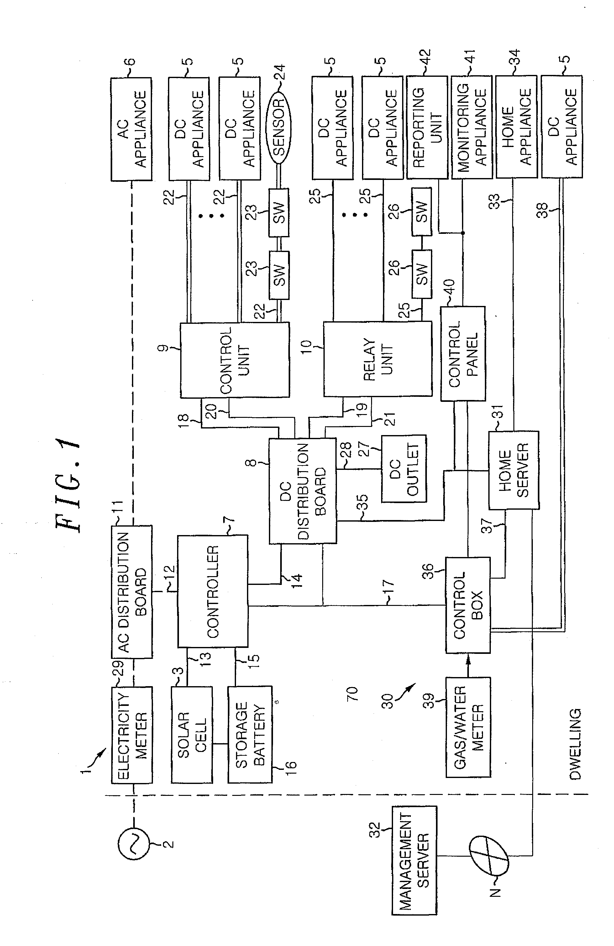
[0058]As shown in FIG. 1, in a dwelling as a power supply destination, a power supply system 1 for supplying a power to various types of appliances installed at home (illumination devices, air conditioners, electric home appliances, audio and visual appliances or the like) is provided. The power supply system 1 supplies not only a power from a commercial AC (Alternating Current) power source 2 (AC power source) for home use but also a power from a solar cell 3 which generates a power by using solar light, to various types of appliances. The power supply system 1 supplies a power to an AC appliance 6 configured to receive the AC power from the commercial power source (AC power source) and b...


PUM


Abstract

A power distribution system includes: a remote electricity monitoring device which is provided at each power supply destination, and remotely reads, via communication means, an consumed power amount and an surplus power amount stored in a power storage device at each supply destination; and a management server which manages the power supply of each supply destination while collecting, via the communication means, the consumed power information and the surplus power information, both of which are read by the remote electricity monitoring device. The management server distributes the power among the supply destinations in line with the relationship between the power amounts based on the consumed power information and surplus power information.

Description

FIELD OF THE INVENTION[0001]The present invention relates to a power distribution system for distributing a power supplied to dwellings or the like by using remote electricity monitoring devices installed in the dwellings or the like.BACKGROUND OF THE INVENTION[0002]Conventionally, Japanese Patent Application Publication No. 2005-070869 discloses a remote electricity monitoring device. That is, with this device, a register displaying accumulated electricity consumption and a rotating disc of an induction type watt-hour meter previously installed are imaged by an imaging unit. Then, through the pattern recognition on respective obtained images, the accumulated electricity consumption displayed on the register and accumulated electricity consumption estimated from the rotation of the rotating disc are obtained, so that the accumulated electricity consumption of the induction type watt-hour meter can be monitored based on the obtained accumulated electricity consumption. Further, the m...

Claims


Application Information

Patent Timeline
Patent Type & Authority Patents(United States)
IPC IPC(8): G06F1/26G06Q50/00G06Q50/06H02J3/00H02J13/00
CPCH02J13/0079H02J3/32Y04S10/14H02J13/00028H02J13/00034Y02E60/00Y04S20/221Y04S20/222Y04S20/242Y02B70/30Y02B70/3225
Inventor YONEDA, SATSUKIMORI, SHINICHI
Owner PANASONIC CORP
Why Eureka
Try Eureka