Vehicle-mounted radar device

a radar device and vehicle-mounted technology, applied in the direction of measurement devices, using reradiation, instruments, etc., can solve the problems of inability to precisely distinguish the size of objects, restrictions on the size of radar devices, and inability to enlarge the aperture area of antennas in radar devices, etc., to achieve simple configuration, large aperture area, and high azimuth resolution

Inactive Publication Date: 2014-10-21
TOYOTA JIDOSHA KK
View PDF27 Cites 1 Cited by
  • Summary
  • Abstract
  • Description
  • Claims
  • Application Information

AI Technical Summary

Benefits of technology

[0020]With the first aspect, even when the aperture area of an antenna cannot be enlarged (due to restrictions on the size of those to be mounted), since a synthetic aperture processing is conducted on the reception signals obtained from the radar device by utilizing the movement of the vehicle, properties equivalent to that obtained if receptions are conducted with a radar device having a large aperture area can be achieved. Therefore, with a simple configuration, a vehicle-mounted radar device capable of obtaining a high azimuth resolution can be provided.
[0021]With the second aspect, since information indicating the reception signals and the positions of the vehicle are stored in the storage unit as a set, the synthetic aperture processing can be conducted easily.
[0022]With the third aspect, since the time interval of the obtained reception signals can be taken into consideration in the synthetic aperture processing, the synthetic aperture processor can conduct the synthetic aperture processing on the reception signals in a further precise manner.
[0023]With the fourth aspect, even when the direction of the vehicle changes, the synthetic aperture processing can be conducted on the reception signals in a further precise manner.
[0024]With the fifth aspect, even when, for example, the movement of the vehicle becomes complicated due to a steering operation performed by a driver, the synthetic aperture processing can be conducted on the reception signals in a further precise manner.
[0025]With the sixth aspect, a synthetic aperture processing envisioned for targets that are desired to be separately detected can be achieved. Thus, for example, when envisioned is a situation requiring a higher azimuth resolution such as when parking a vehicle in a vacant space of a parking area, a larger number can be set in advance for the reception signals used in the synthetic aperture processing.

Problems solved by technology

In addition, in a case where it is determined that there is a risk of a collision between the own-vehicle and the object, or in other cases, the vehicle-mounted object detecting device controls various devices built into the own-vehicle.
Although a radar device included in a general vehicle-mounted object detecting device may recognize an existence of an object, it is often impossible to precisely distinguish the size of the object (for example, a vehicle width of another vehicle).
One of such reasons is an inability to enlarge an aperture area of an antenna in the radar device; since, in a case with a radar device that uses radio waves, a resolution of an angle direction is proportional to an aperture area of the antenna.
More specifically, since the radar device included in the vehicle-mounted object detecting device is envisioned to be mounted on a vehicle, there are restrictions for the size of the radar device, and the aperture area of the antenna cannot be enlarged.

Method used


Image

  • Vehicle-mounted radar device
  • Vehicle-mounted radar device
  • Vehicle-mounted radar device

Examples


Embodiment Construction

[0042]With reference to the following drawings, a vehicle-mounted radar device according to one embodiment of the present invention will be described. It should be noted that, in the present embodiment, description is provided envisioning a case in which a Driver Support System (DSS) including the vehicle-mounted radar device is mounted on a vehicle (in the following, referred to as an own-vehicle mv).

[0043]First, a general outline of the vehicle-mounted radar device according to the present embodiment will be briefly described.

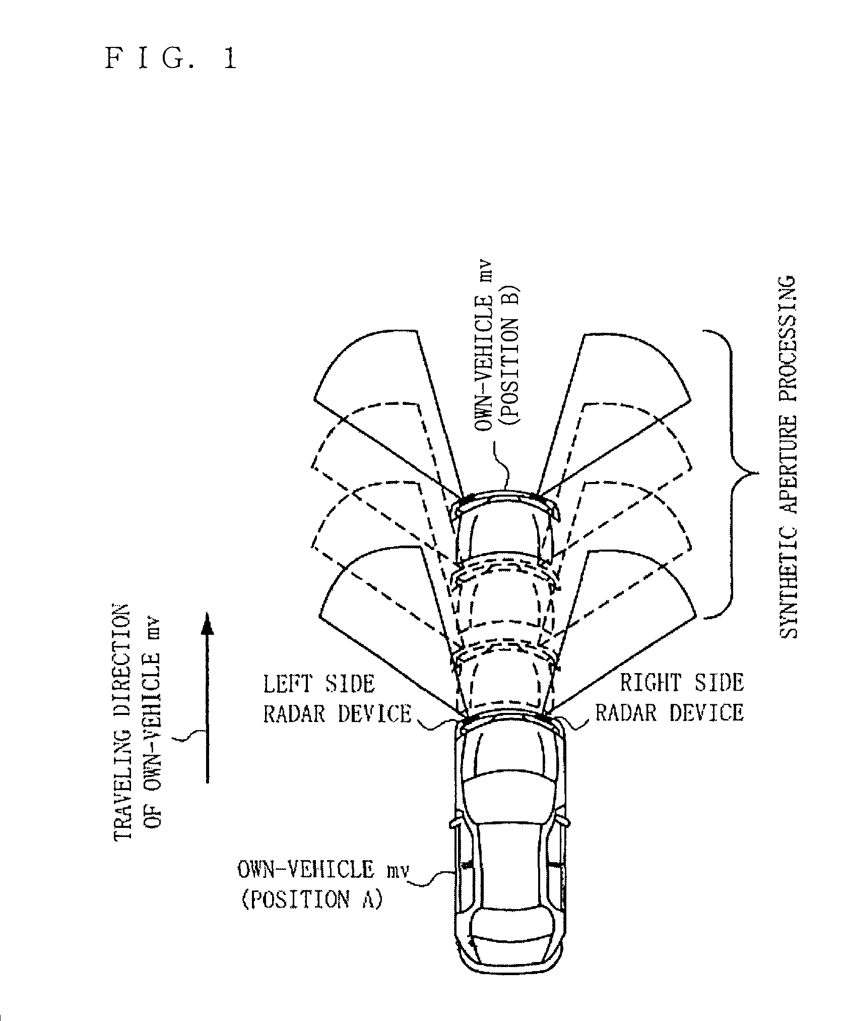
[0044]With regard to a radar device mounted on the own-vehicle mv, the radar device moves as the own-vehicle mv moves (travels). FIG. 1 is a figure showing a movement of the own-vehicle mv and movements of radar devices mounted on the own-vehicle mv. It should be noted that, in FIG. 1, the radar devices are mounted on the right and left front portions of the own-vehicle mv as one example (a right side radar device and a left side radar device shown in FIG. 1)...


PUM


Abstract

Provided is a vehicle-mounted radar device capable of obtaining a high azimuth resolution with a simple configuration.The vehicle-mounted radar device is mounted on a vehicle, and includes: a detector for irradiating a periphery of the vehicle with electromagnetic waves, and for outputting a reception signal obtained from reflected waves that are reflected from an object that exists in the periphery of the vehicle; a vehicle information calculator for calculating information related to a movement of the vehicle with a use of vehicle information of the vehicle; a storage unit for storing a plurality of the reception signals outputted by the detector at different time points; and a synthetic aperture processor for conducting a synthetic aperture processing on the reception signals obtained by the vehicle at different positions, based on the information related to the movement of the vehicle.

Description

TECHNICAL FIELD[0001]The present invention relates to a vehicle-mounted radar device, and more specifically, relates to a vehicle-mounted radar device which is mounted on a vehicle and which detects an object approaching from a periphery of the vehicle.BACKGROUND ART[0002]Conventionally, as one that detects an object that is approaching from the front or a side of a vehicle of one's own, a vehicle-mounted object detecting device which is mounted on the own-vehicle is known. Specifically, the vehicle-mounted object detecting device detects an object approaching the own-vehicle by means of a radar device (for example, a millimeter wave radar device). Then, based on the detection result, the vehicle-mounted object detecting device determines the risk of a collision between the own-vehicle and the object. In addition, in a case where it is determined that there is a risk of a collision between the own-vehicle and the object, or in other cases, the vehicle-mounted object detecting device...

Claims


Application Information

Patent Timeline
Patent Type & Authority Patents(United States)
IPC IPC(8): G01S13/58G01S13/93G01S13/00G01S13/87G01S13/90G01S13/931
CPCG01S2013/9378G01S13/58G01S2013/9353G01S13/589G01S13/931G01S13/87G01S13/90G01S2013/9375G01S2013/93272G01S2013/932G01S2013/93271G01S13/9089G01S13/9041
Inventor YAMADA, NAOYUKI
Owner TOYOTA JIDOSHA KK
Why Eureka
Try Eureka