Apparatus for disconnecting solder joints between two welded surfaces

a technology of solder joints and disconnectors, which is applied in the direction of soldering apparatus, manufacturing tools, instruments, etc., can solve the problems of unstable laser energy for melting the solder joint, remains of the solder material to block the outlet of the handling device, and the maintenance time and maintenance workload would be short, so as to improve work efficiency, the effect of stabilizing the laser energy

Active Publication Date: 2014-10-28
SAE MAGNETICS (HK) LTD
View PDF3 Cites 0 Cited by
  • Summary
  • Abstract
  • Description
  • Claims
  • Application Information

AI Technical Summary

Benefits of technology

[0013]One aspect of the present invention is to provide an apparatus for disconnecting solder joints between two welded surfaces in a disk drive unit, which can shorten maintenance time and maintenance workload and improve work efficiency, furthermore stabilize the laser energy and reduce its losing.
[0026]Based on the above design, on one hand, due to the hole is formed on the glass cover which acts as a way of airflow, thus the remains of the melted solder material which are absorbed in the first passage can not be gathered on the surface of the glass cover under the power of the airflow. As a result, the losing of the laser beams passing the glass cover is little even undergoing a long working time. On the other hand, as at least two pumping devices are connected with the holder, thus the suction force is enlarged, therefore little remain of the melted solder material is left on the side walls of the holder. Furthermore, as the laser device and the solder material removal device are separated, thus the optical axis of the laser device can be adjusted exactly and easily, which can stabilize the laser beams and improve the using efficiency of the laser beams.

Problems solved by technology

During the process of forming the solder joints, defects would be generated due to fine positioning difference between the soldering device and the welded surfaces, or laser energy for melting the solder joint is unstable, and so on.
Furthermore, due to only one pressure connection 240 is connected with the handling device 230, thus the suction force of the pumping device is not sufficient, which may cause remains of the solder material to block on the outlet of the handling device 230.
However, due to the structure of the handling device 230 is unitary, that is, the outlet and the handling device 230 are integrative, thus it's quite inconvenient to clean or change the handling device 230, which may spend a lot of time and workload.

Method used


Image

  • Apparatus for disconnecting solder joints between two welded surfaces
  • Apparatus for disconnecting solder joints between two welded surfaces
  • Apparatus for disconnecting solder joints between two welded surfaces

Examples


Embodiment Construction

[0039]Various preferred embodiments of the invention will now be described with reference to the figures, wherein like reference numerals designate similar parts throughout the various views. As indicated above, the invention is directed to an apparatus for disconnecting solder joints between two welded surfaces in a disk drive unit, which can shorten maintenance time and maintenance workload and improve work efficiency, furthermore reduce and stabilize the laser energy.

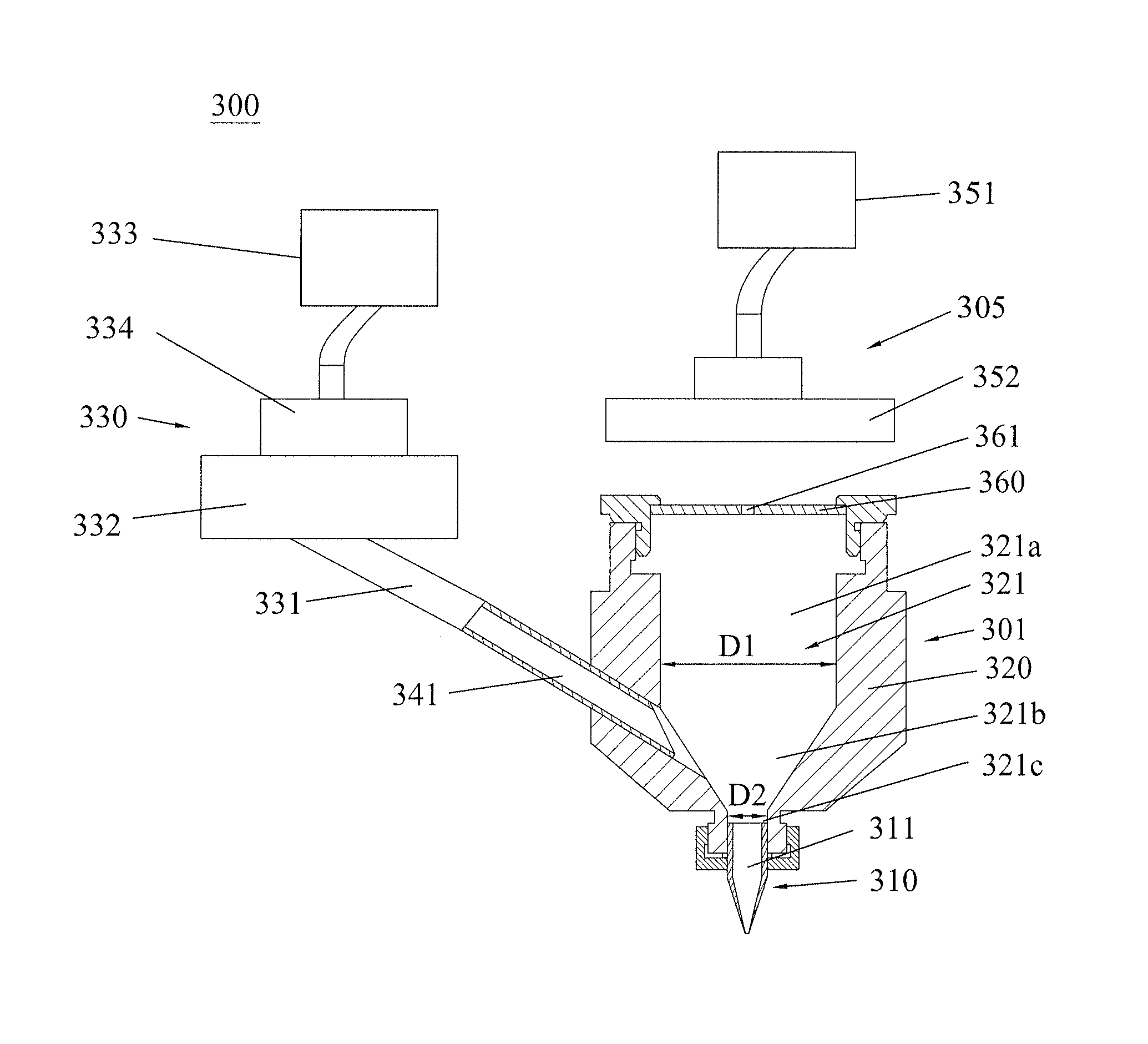
[0040]FIGS. 3a-4 are cross section views of an apparatus for disconnecting solder joints between two welded surfaces in a hard disk drive according to one embodiment of the present invention. As shown, the apparatus 300 includes a solder material removal device 301 and a laser device 305. Concretely, the solder material removal device 301 includes a nozzle device 310 having a first passage 311, a holder 320 holding the nozzle device 310 and at least two pumping devices 330 connected to the holder 320.

[0041]Concretely...


PUM

PropertyMeasurementUnit
flexibleaaaaaaaaaa
pressureaaaaaaaaaa
diameteraaaaaaaaaa

Abstract

An apparatus for disconnecting solder joints between two welded surfaces includes a laser device for emitting laser beams to a solder joint, and a solder material removal device. And the solder material removal device includes a nozzle device having a first passage, a holder holding the nozzle device and having a second passage communicated with the first passage, and at least two pumping devices connected to the holder to pump the melted solder material out from the nozzle device and the holder. The laser device and the solder material removal device are separated, a glass cover with a hole formed thereon is covered on the top of the holder, and the laser device is located above the glass cover and separated from the holder. The present invention can shorten maintenance time and maintenance workload and improve work efficiency, furthermore reduce and stabilize the laser energy.

Description

[0001]This application claims priority to Chinese Application No. 201210236404.1 filed 9 Jul. 2012, the entire contents of which is hereby incorporated by reference.FIELD OF THE INVENTION[0002]The present invention relates to an apparatus for disconnecting solder joints between two welded surfaces in a disk drive unit and, more particularly, to an apparatus for disconnecting solder joints between a head gimbal assembly (HGA) and a flexible printed circuit (FPC) in a defective head stack assembly (HSA).BACKGROUND OF THE INVENTION[0003]Hard disk drives are information storage devices that use thin film magnetic media to store data. Referring to FIG. 1a, a typical hard disk drive 1 in prior art comprises a head stack assembly (HSA) 10 with slider 11 (shown in FIG. 1b) thereon, a magnetic disk 12 mounted on a spindle motor 13 which causes the magnetic disk 12 to spin, and a motor base 14 to enclose the above-mentioned components.[0004]The slider 11 flies over the surface of the magnetic...

Claims


Application Information

Patent Timeline
Patent Type & Authority Patents(United States)
IPC IPC(8): B23K1/018B23K1/18B23K26/14
CPCG11B5/4806G11B5/486G11B5/4853G11B5/50
Inventor ZHAO, QIN PINGCHOU, SHEN KUANG SIDNEY
Owner SAE MAGNETICS (HK) LTD
Why Eureka
Try Eureka