Geothermal wind system

a wind turbine and geothermal technology, applied in the direction of reciprocating combination engines, renewable energy generation, greenhouse gas reduction, etc., to achieve the effect of preventing human or larger wildlife endangerment and preventing wildlife harm

Inactive Publication Date: 2014-11-04
SIMPSON LARRY C
View PDF5 Cites 15 Cited by
  • Summary
  • Abstract
  • Description
  • Claims
  • Application Information

AI Technical Summary

Benefits of technology

[0061]U.S. Pat. No. 5,445,095, Jul. 29, 1995, Reed, J. C. & Bushnell, D. M. Polymer / Riblet Combination for Hydrodynamic Skin Friction Reduction: A process for reducing skin friction and inhibiting the effects of liquid turbulence in a system involving the flow of a liquid along the surface of a body, e.g. a marine vehicle, includes injecting a drag reducing polymer into the valleys of adjacent, evenly spaced, longitudinal grooves extending along the length of the surface of the body, so that the rate of diffusion of the polymer from individual grooves into the liquid flow is predictably controlled by the groove dimensions. When the polymer has diffused over the tips of the grooves into the near wall region of the boundary layer, the polymer effectively reduces the turbulent skin friction. A substantial drag reducing effect is achieved with fewer polymers than must be used to lower skin friction when the surface of the body is smooth.
[0083]18. Apertures could allow the tunnels to be closed for maintenance, and small bypass tunnels could be opened to allow some airflow. All entrances would be contained within large smooth funnels ideally made of concrete to allow passage of air with the least amount of dust. The funnels will be covered with outwardly convex fauna grates to prevent harm to wildlife including bats and birds. The upper openings may be extended several meters and surrounded by fencing, as well, to prevent human or larger wildlife endangerment.

Problems solved by technology

This system is non-polluting and non-carbon producing, non-water using, with low noise emissions and a small footprint with widespread possible usage.

Method used


Image

  • Geothermal wind system
  • Geothermal wind system
  • Geothermal wind system

Examples


Embodiment Construction

[0119](All depictions are representative, not to scale, and may not show the exact field design of the numerous embodiments of the art.)

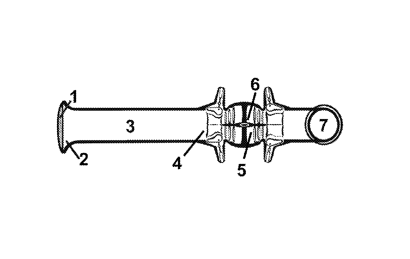
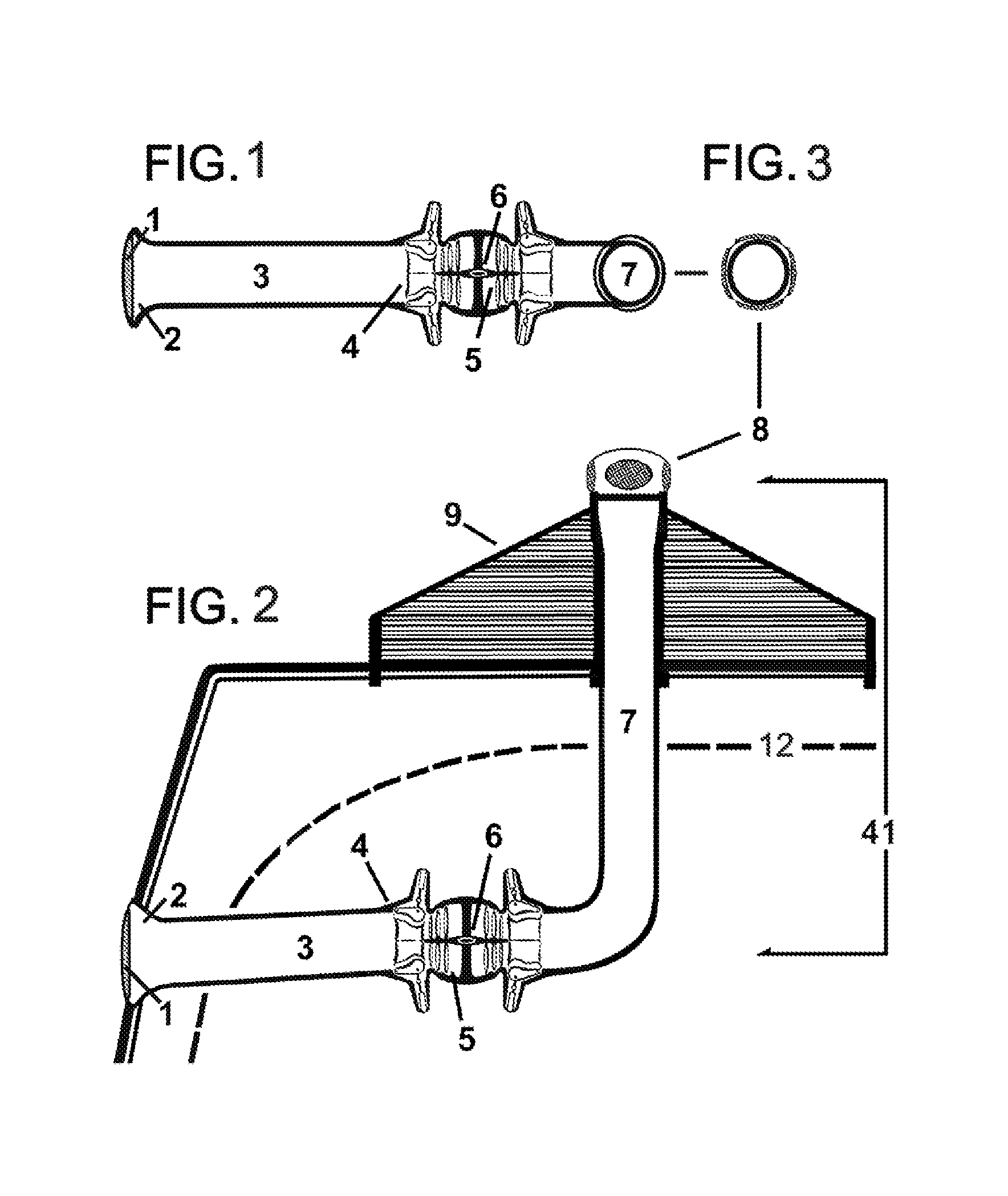
[0120]54. FIG. 1, FIG. 2 and FIG. 3: FIG. 1. Horizontal and FIG. 2. Vertical Schematics of Low Geothermal Temperature Mode GWS: On days cooler than the geothermal temperature, air is pulled into the lower portal (2) by warmer lighter air rising to the upper portal. It first passes through a Fauna Protection Grate (1) built for the purpose of preventing entry by animals or wind blown debris, affixed to a Funnel Shaped Portal (2) which is an infuser / diffuser to prevent excessive suction of objects into the Portal and to make up for wind resistance caused by the Fauna Protection Grate.

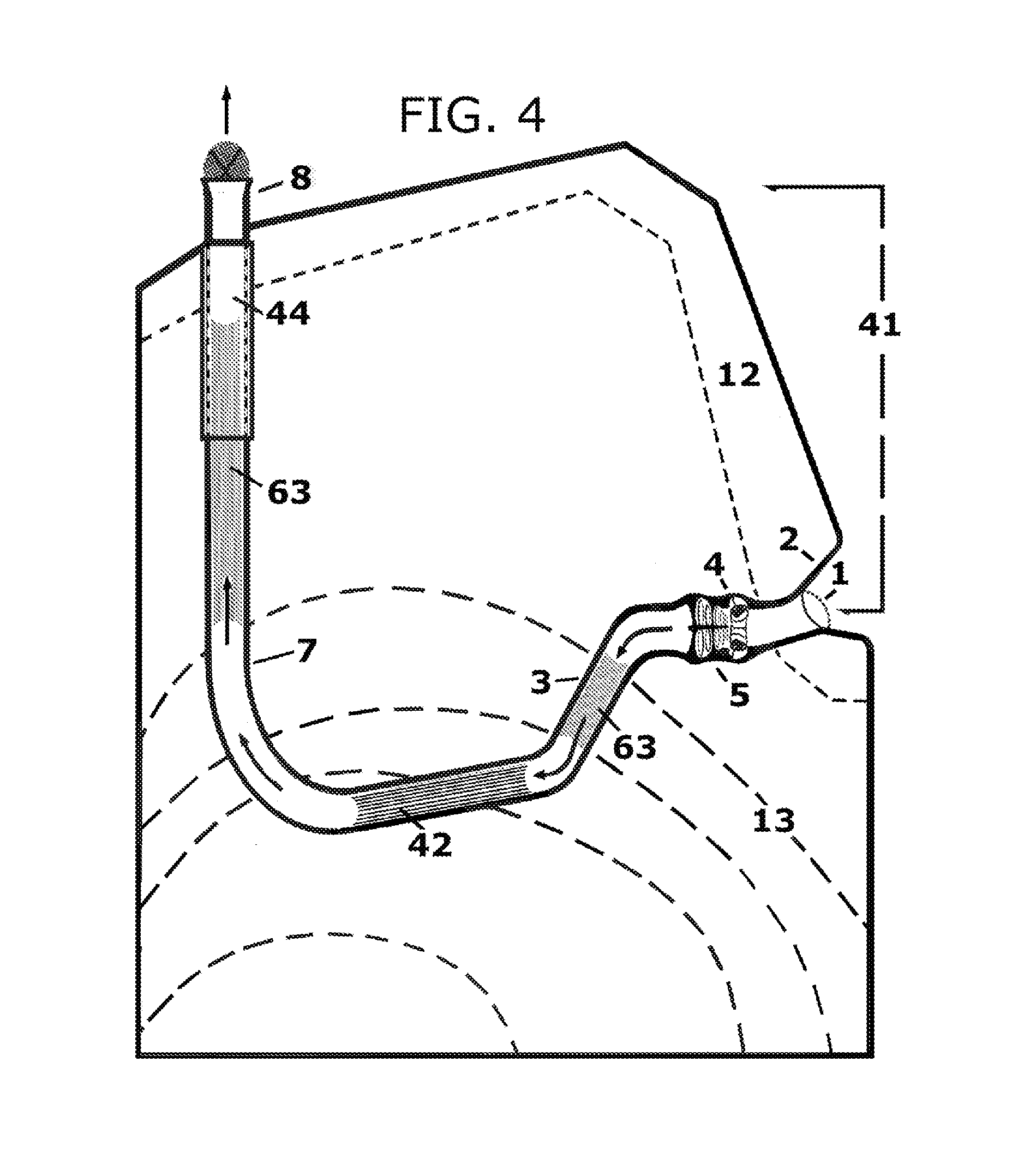
[0121]55. The air travels 60 meters (200 ft) to temperature stasis beyond the influence of outside temperatures (12). There, a natural temperature exchange takes place between the surface of the tunnel and the air in the Heat Exchange Tunnel (3). This tunnel should be smo...


PUM


Abstract

The Geothermal Wind System is a hybrid power production system using geothermal transfer of heat between native rock and an air mass circulating between two or more portals of substantially different vertical elevations by use of the stack effect and the buoyancy of heated air or gravity pulling cooled air to turn one or more wind turbines which drive one or more generators. This wind speed can be improved by use of a venturi valve in close proximity to the turbine(s). A novel example of an aerodynamic, adjustable radial venturi is also herein incorporated. Two modes of the GWS are herein described, one used at shallow depths having geothermal temperatures approximating the average exterior climate, and the second used with geothermal temperatures found at greater depths at substantially higher than outside temperatures. The GWS is a non-polluting, non-carbon burning, non-water-dependent power production system easily implemented in third world countries.

Description

BACKGROUND OF THE INVENTION[0001]This invention relates to electrical power generation, more particularly to a novel hybrid power generating system to be known as the Geothermal Wind System (GWS), where a tunnel and shaft provide a circulating wind system to power turbines which generate electricity or by transferred mechanical energy turn electrical generators, using a passive geothermal heat exchange to create gravity induced buoyancy of air. There are two modes based on the same principle from which many embodiments of GWS can be created: The Low Temperature Mode harnesses geothermal temperature that is approximately the same as the yearly average of the outside temperature allowing bi-directional winds to flow upward or downward depending on the outside temperature. The High Temperature Mode is used where the geothermal temperature is greater than 49 C degrees or higher than the highest external temperature. This mode of high geothermal temperature always generates wind upward. ...

Claims


Application Information

Patent Timeline
Patent Type & Authority Patents(United States)
IPC IPC(8): F03D3/00F03G7/00F01B21/04F24J3/08F03D9/00
CPCF03G7/04Y02E10/14F03D9/00Y02E10/10F03D9/002F03G7/00F05B2240/131F03D1/04F03D3/00Y02E10/72F24J3/08Y02E10/725F03D1/02F03D9/25F03D9/34F24T10/10Y02E10/728Y02E10/74
Inventor SIMPSON, LARRY, CLARK
Owner SIMPSON LARRY C
Why Eureka
Try Eureka