Chemical vapor deposition apparatus capable of controlling discharging fluid flow path in reaction chamber

a technology of discharging fluid and reaction chamber, which is applied in chemical vapor deposition coating, coating, metallic material coating process, etc., can solve the problems of undesired particles in the processing chamber, difficult to obtain thin layers having a uniform layer quality or a uniform layer thickness distribution, and negatively influence the quality of thin layers

Inactive Publication Date: 2014-11-04
LIGADP
View PDF15 Cites 267 Cited by
  • Summary
  • Abstract
  • Description
  • Claims
  • Application Information

AI Technical Summary

Benefits of technology

[0009]The present invention provides a chemical vapor deposition apparatus having a constitution that can control the width of the gas discharge path between the susceptor and the wall of the processing chamber without again designing and manufacturing the chemical vapor deposition apparatus.

Problems solved by technology

When the atmosphere temperature drops below the evaporation temperature of the residual gas being discharged, this could induce formation of undesired particles in the processing chamber.
The undesired particles may drop onto the substrate in the processing chamber, and it would create difficulties in acquiring the thin layer having a uniform layer quality or a uniform layer thickness distribution.
Also, these undesired particles could attach onto a gas discharge path, causing the warm-keeping effect.
This warm-keeping effect refers to the temperature difference created between the preset and the actual temperatures of the processing chamber, and this temperature difference will negatively influence the quality of the thin layer.
Furthermore, when uniform flow distribution of processing gas is not achieved, for example, due to a vortex generated in the gas discharge path, even more undesirable particles may be generated.
One reason behind the causes of vortex generation is the improper width of the gas discharge path between the susceptor and the nearby wall of the processing chamber.
In a conventional MOCVD apparatus, the width of the gas discharge path between the susceptor and the wall of the processing chamber is fixed by design such that it would not be possible to control the width of the gas discharging path.

Method used


Image

  • Chemical vapor deposition apparatus capable of controlling discharging fluid flow path in reaction chamber
  • Chemical vapor deposition apparatus capable of controlling discharging fluid flow path in reaction chamber
  • Chemical vapor deposition apparatus capable of controlling discharging fluid flow path in reaction chamber

Examples


Embodiment Construction

[0020]The present invention will now be described more fully with reference to the accompanying drawings, in which exemplary embodiments of the present invention are shown. The present invention may, however, be embodied in different forms and should not be construed as limited to the embodiments set forth herein. Rather, these embodiments are provided so that this disclosure will be thorough and complete, and will fully convey the scope of the present invention to those skilled in the art. In the figures, the dimensions of layers and regions may be exaggerated for clarity of illustration. Like reference numerals in the drawings denote like elements.

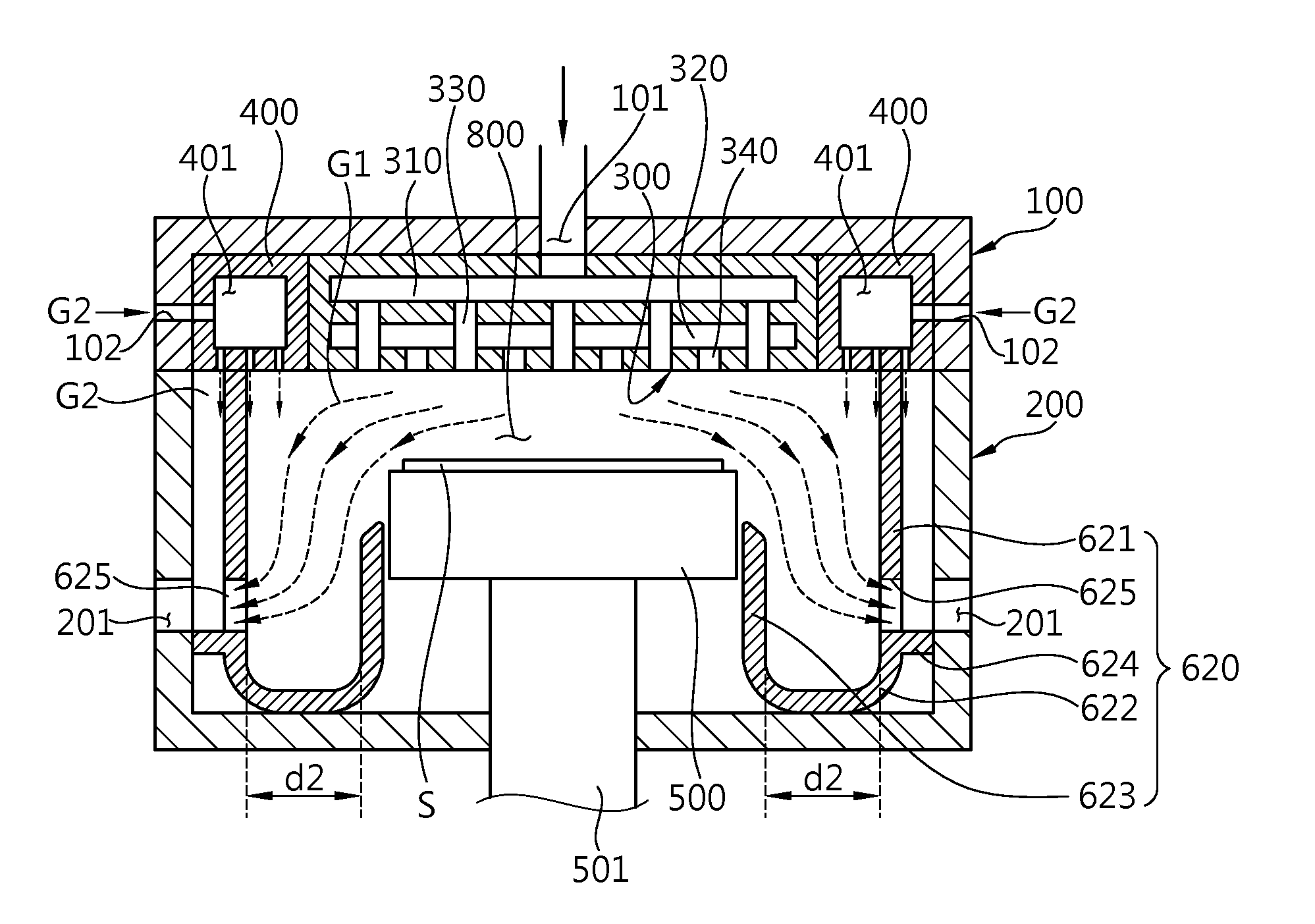
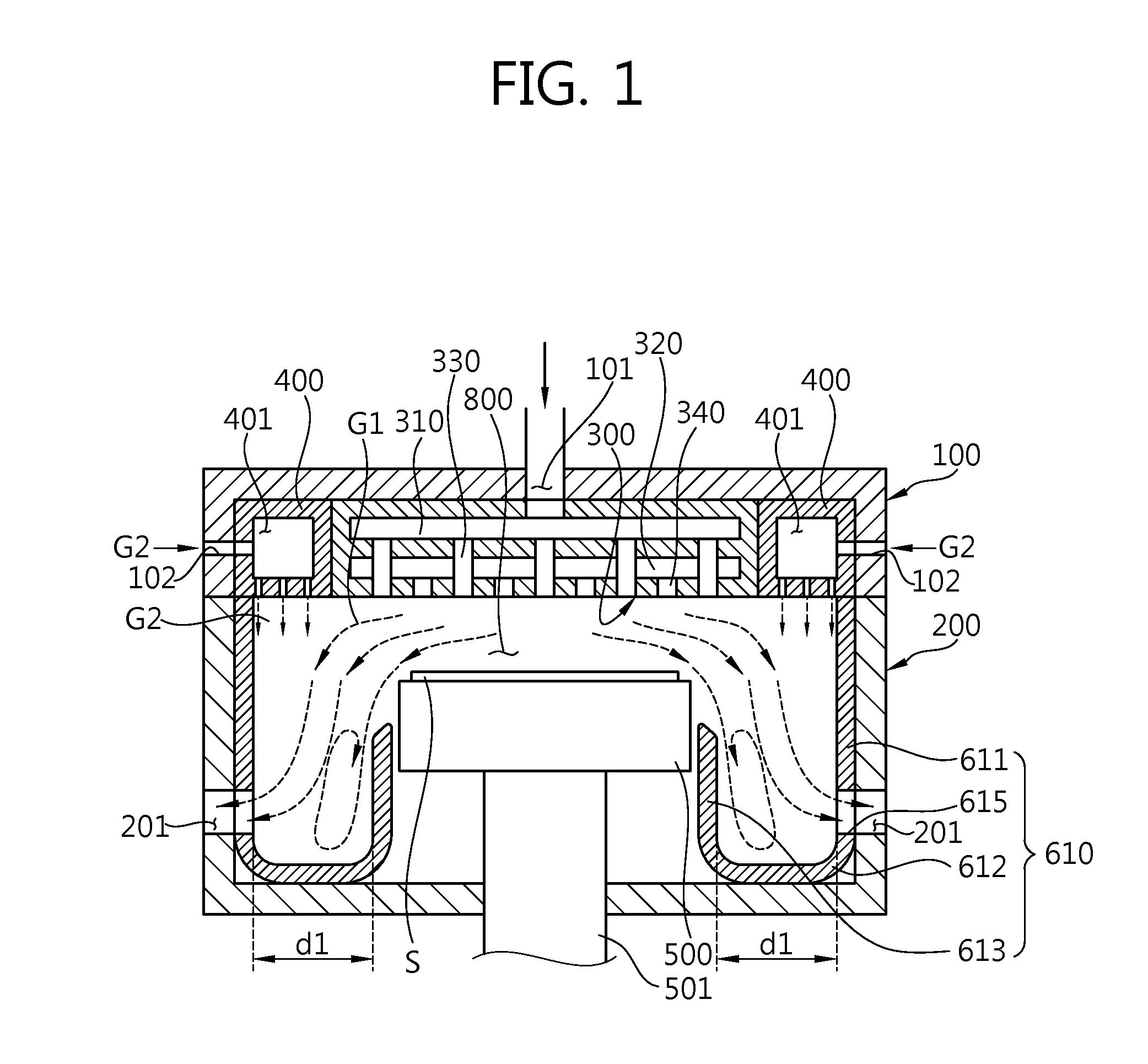
[0021]FIG. 1 is a cross-sectional view of a chemical vapor deposition apparatus according to an embodiment of the present invention showing a guide unit 610 (which can be replaced as it will be explained in more detail below with respect to FIGS. 5-7) in place inside a chemical vapor deposition apparatus comprising a first chamber 100 an...


PUM

PropertyMeasurementUnit
distanceaaaaaaaaaa
shapeaaaaaaaaaa
diameteraaaaaaaaaa

Abstract

A chemical vapor deposition apparatus is equipped to control the width of a gas discharge path between a susceptor and an inner surface of a chamber without having to resort to redesign and remanufacturing of the apparatus. The chemical vapor deposition apparatus includes: a chamber; a susceptor positioned inside the chamber and on which a substrate can be loaded; a shower head injecting a processing gas toward the substrate; and a guide unit detachably installed inside the chamber to guide the processing gas such that the processing gas injected from the shower head is discharged through a chamber hole formed in the chamber.

Description

CROSS-REFERENCE TO RELATED PATENT APPLICATION[0001]This application claims the benefit of Korean Patent Application No. 10-2009-0068831, filed on Jul. 28, 2009, in the Korean Intellectual Property Office, the disclosure of which is incorporated herein in its entirety by reference.BACKGROUND OF THE INVENTION[0002]1. Field of the Invention[0003]The present invention relates generally to a semiconductor manufacturing apparatus for forming a thin layer, and more particularly to a chemical vapor deposition apparatus.[0004]2. Description of the Related Art[0005]Metal organic chemical vapor deposition (MOCVD) is a technique for depositing a thin layer onto a substrate by reacting, for example, a group-III gas and a group-V gas with the substrate in a heated reactor. Using MOCVD, it is possible to build up many thin layers with the ability to precisely control the thickness or chemical composition of each thin layer. As such MOCVD is widely used in semiconductor manufacturing processes.[000...

Claims


Application Information

Patent Timeline
Patent Type & Authority Patents(United States)
IPC IPC(8): C23C16/455
CPCC23C16/45574C23C16/45572C23C16/4412C23C16/45565H01L21/205
Inventor HAN, MYUNG, WOO
Owner LIGADP
Why Eureka
Try Eureka