High efficiency, low voltage, low L-band, mega-watt class magnetron

Inactive Publication Date: 2014-11-04
THE UNITED STATES OF AMERICA AS REPRESETNED BY THE SEC OF THE AIR FORCE
View PDF4 Cites 9 Cited by
  • Summary
  • Abstract
  • Description
  • Claims
  • Application Information

AI Technical Summary

Benefits of technology

[0009]It is another object of the invention to accomplish the foregoing o

Problems solved by technology

Current commercially available magnetrons suitable for use in such critical military applications as providing countermeasures for impr

Method used


Image

  • High efficiency, low voltage, low L-band, mega-watt class magnetron
  • High efficiency, low voltage, low L-band, mega-watt class magnetron
  • High efficiency, low voltage, low L-band, mega-watt class magnetron

Examples


Embodiment Construction

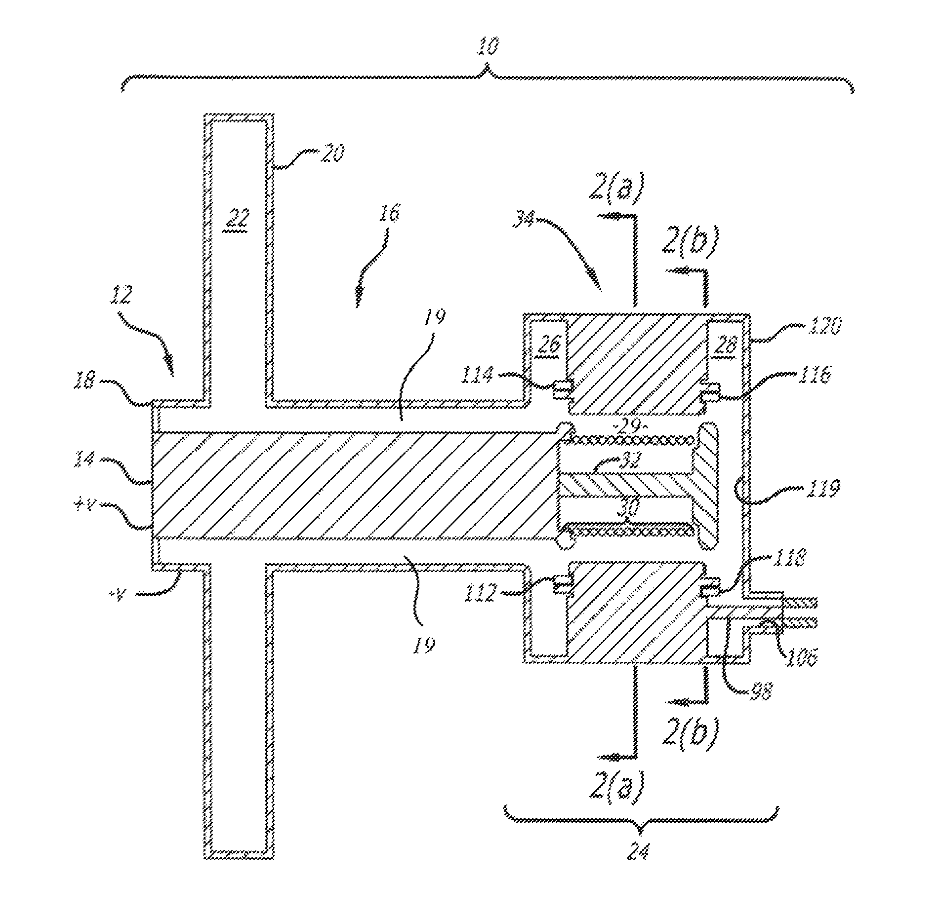
[0022]The present invention will be seen to provide a magnetron capable of providing megawatt power at conventional, non-relativistic diode voltages (less than 100 kV). Previously, the design of a magnetron capable of such performance was hindered by perceived difficulties. Concern about (breakdown) axial field stresses upon straps added to anode vanes for purposes of mode separation. An additional concern has centered about the issue of heating of the cathode. As described below, the inventors have designed a magnetron that offers architecture capable of sustaining the perceived stresses and heating to accomplish megawatt power outputs at conventional diode voltages. Simulations based upon such architecture are discussed to prove the efficacy of the inventors' magnetron design.

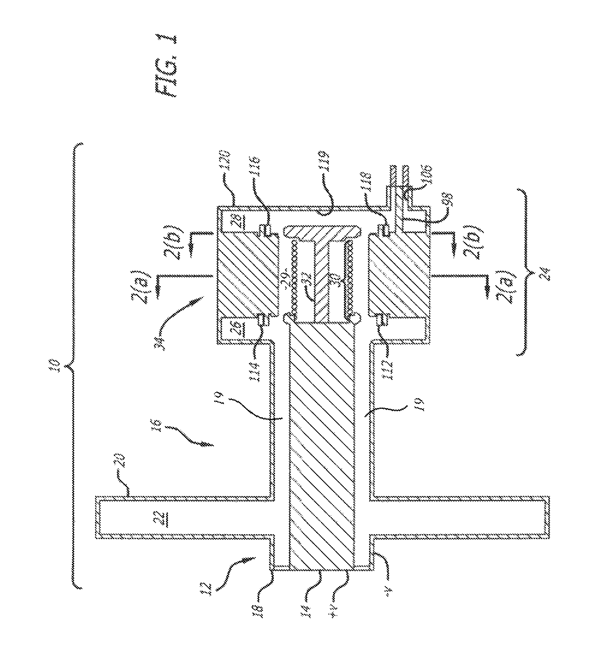
[0023]Turning now to the drawings, FIG. 1 is a side sectional view of a magnetron 10 in accordance with the invention. A voltage potential can be applied at an upstream end 12 that communicates with a coaxial...


PUM


Abstract

A conventional (non-relativistic) magnetron provides megawatt-levels of power. The magnetron includes a fourteen vane slow wave structure that surrounds a fourteen turn helical cathode. An upstream coaxial waveguide is surrounded by a dish-shaped flange that accommodates a reflector chamber in communication with an upstream void and a downstream interaction chamber. The vanes of the slow wave structure are shaped to define fourteen resonant chambers therebetween with each of the resonant cavities having a wedge portion in communication with a neck portion.

Description

GOVERNMENT INTEREST[0001]The conditions under which this invention was made are such as to entitle the Government of the United States under paragraph 1(a) of Executive Order 10096, as represented by the Secretary of the Air Force, to the entire right, title and interest therein, including foreign rights.BACKGROUND OF THE INVENTION[0002]1. Technical Field[0003]The present invention relates to magnetrons. More particularly, this invention pertains to a compact conventional (non-relativistic) magnetron suitable for numerous military and industrial applications.[0004]2. Background Art[0005]The magnetron is a crossed-field device in which electric fields (RF and d.c.) are perpendicular to a static magnetic field. It is recognized that numerous military and industrial applications exist for employing such a device capable of generating more than 1 Mega-watt of RF power near L-band with efficiencies of 85 percent or more.[0006]Current commercially available magnetrons suitable for use in ...

Claims


Application Information

Patent Timeline
IPC IPC(8): H01J23/36H01J25/50
CPCH01J25/50H01J23/18H01J23/36H01J25/587
Inventor FLEMING, TIMOTHY PAULLAMBRECHT, MICHAEL RAYMONDMARDAHL, PETER JEROMEKEISLING, JOHN DAVIS
Owner THE UNITED STATES OF AMERICA AS REPRESETNED BY THE SEC OF THE AIR FORCE
Why Eureka
Try Eureka