Wavelength multiplexed optical system with multimode optical fibers

a multi-mode fiber and wavelength multiplexing technology, applied in the field of optical fiber transmission, can solve the problems of complex adaptive optics system, high cost, and difficulty in reaching such bitrates with a single transmission channel

Active Publication Date: 2014-11-04
DRAKA COMTEQ BV
View PDF170 Cites 8 Cited by
  • Summary
  • Abstract
  • Description
  • Claims
  • Application Information

AI Technical Summary

Benefits of technology

[0032]Moreover, each multimode modal dispersion compensation optical fiber typically possesses an optimized index profile such that its modal dispersion for a particular multiplex wavelength (λm) is substantially inversely equal to the modal dispersion induced in the multimode transmission optical fiber during the transmission of that particular multiplex wavelength (λm). In this way, the optical signals received downstream of the multimode modal dispersion compensation optical fiber and the multimode transmission optical fiber have minimized modal dispersion (i.e., the cumulative modal dispersion across the optical system is significantly reduced at the multiplex wavelengths).
[0036]Moreover, in these embodiments the multiplexer and / or the demultiplexer can retain the spatial distribution of the multiplexed or demultiplexed optical signal modes.

Problems solved by technology

It is however difficult to reach such bitrates with a single transmission channel.
Nevertheless, for the foregoing reasons expressed, wavelength multiplexing is not possible directly in a multimode fiber.
The adaptive optics system is however complex and costly, and designed to operate in the C band while most multimode applications are located around 850 nanometers.
The profile and concentrations of dopants for producing such a fiber, however, are difficult to control and the cost of the fiber is thereby increased.
However, the system described in this document is complex to implement.
Such an optical system must be uncomplicated and efficient, and must be implemented with a standard multimode transmission fiber.

Method used


Image

  • Wavelength multiplexed optical system with multimode optical fibers
  • Wavelength multiplexed optical system with multimode optical fibers
  • Wavelength multiplexed optical system with multimode optical fibers

Examples


Embodiment Construction

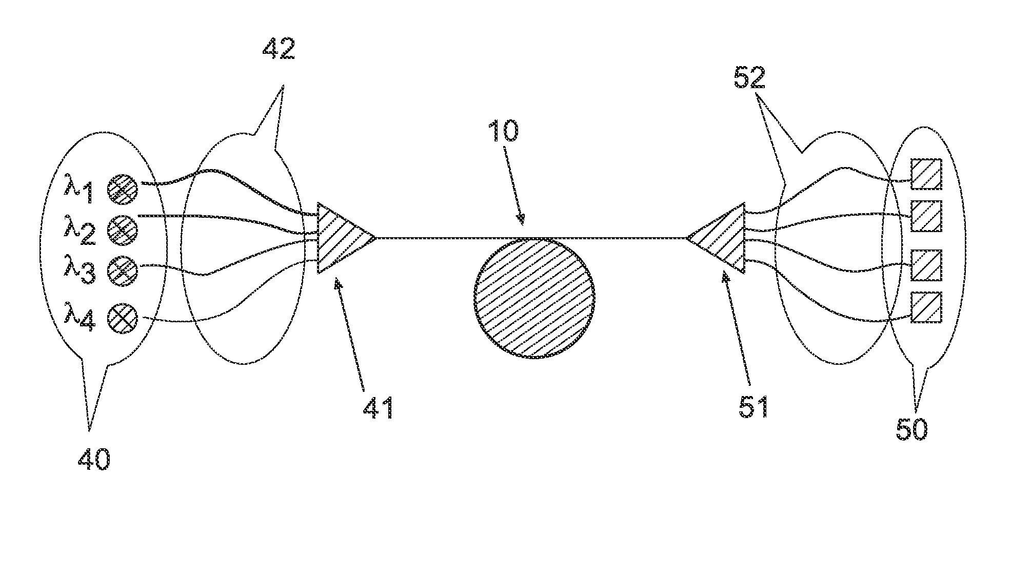
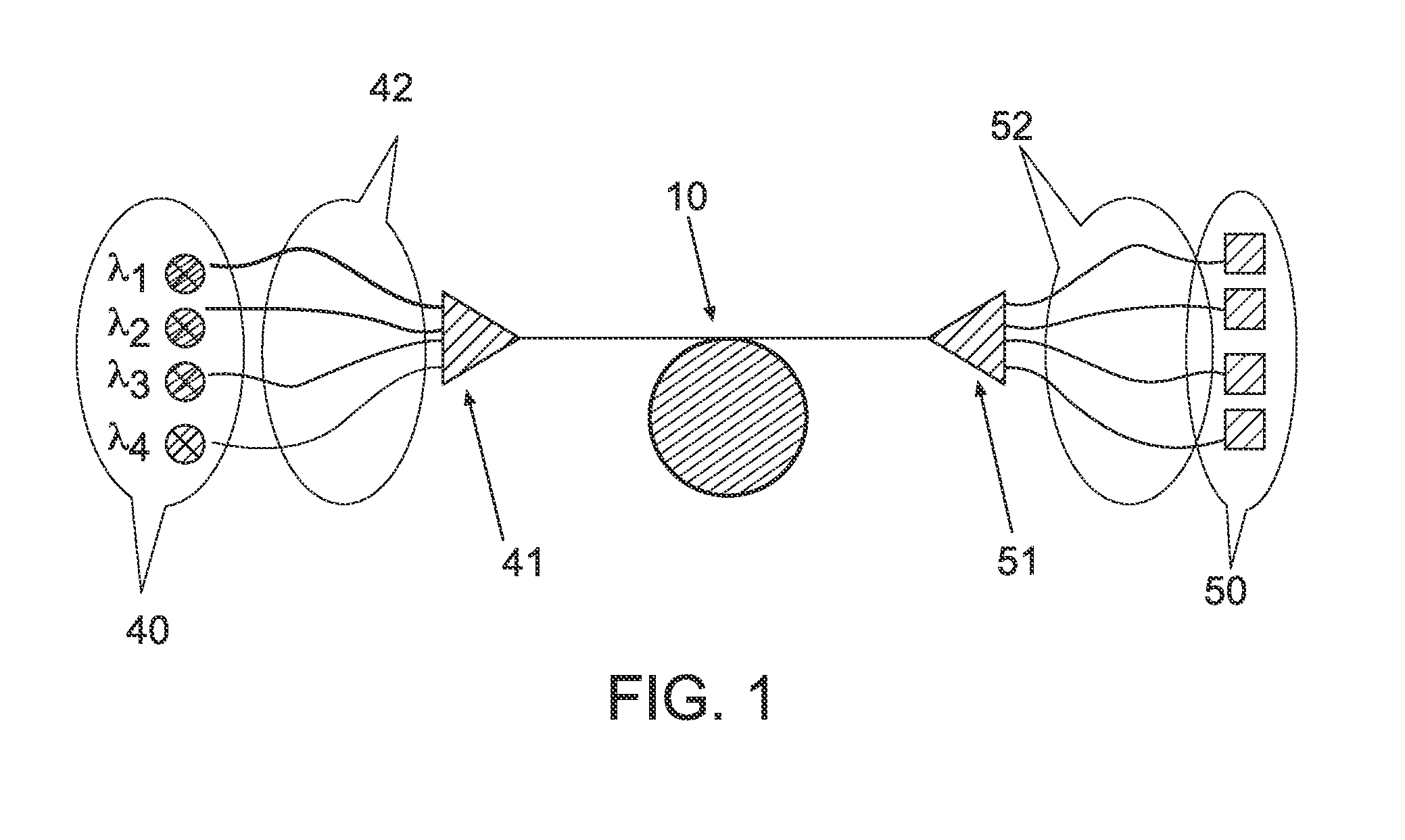
[0045]The present invention proposes an optical system that facilitates the transmission of wavelength multiplexed multimode signals to increase the bitrate of multimode telecommunication networks beyond 10 GbE. The present invention further proposes to achieve this increased bitrate without adversely affecting bandwidth.

[0046]Multimode modal dispersion compensation optical fibers are employed to compensate the modal dispersion that is induced by a multimode transmission optical fiber at some, and perhaps all, of the multiplex wavelengths.

[0047]In one exemplary embodiment, the optical system according to the present invention compensates for the modal dispersion of each multiplex channel upstream of the multiplexer so that the signals received at the output of the multimode transmission fiber have minimized modal dispersion. The transmission system can then ensure a bandwidth greater than or equal to 2000 MHz-km after propagation over 300 meters of multimode fiber and a bandwidth gr...


PUM


Abstract

The present wavelength multiplexed optical system includes a multimode optical fiber that transmits wavelength multiplexed optical signals and a plurality of multimode modal dispersion compensation optical fibers. Each modal dispersion compensation optical fiber can transmit one of the multiplex wavelengths, and each modal dispersion compensation optical fiber has an optimized index profile such that the modal dispersion for the transmitted wavelength is approximately inversely equal to the modal dispersion induced in the multimode optical fiber. The wavelength multiplexed optical system facilitates an increased bitrate without reducing bandwidth.

Description

CROSS-REFERENCE TO PRIORITY APPLICATION[0001]This application claims the benefit of pending French application Ser. No. 08 / 03489 for “Systeme Optique Multiplexe en Longueur D'ondes avec Fibres Optique Multimodes” (filed Jun. 23, 2008, at the French Patent Office), which is hereby incorporated by reference in its entirety.FIELD OF THE INVENTION[0002]The present invention relates to the field of optical fiber transmissions and, more specifically, to multimode fibers used for short-distance optical transmission systems that require large bandwidth.BACKGROUND OF THE INVENTION[0003]Multimode fibers are used for short-distance applications and local networks. The core of a multimode fiber generally has a diameter of approximately 50 microns (μm), compared with approximately 8 to 9 microns (μm) for the core of a single-mode fiber. Thus, for a particular wavelength, several optical modes propagate simultaneously along the fiber, carrying the same information. The bandwidth is directly linke...

Claims


Application Information

Patent Timeline
Patent Type & Authority Patents(United States)
IPC IPC(8): H04B10/2581H04J14/02H04B10/00
CPCH04J14/0279H04J14/02H04B10/2581
Inventor LUMINEAU, YVESMOLIN, DENISGHOLAMI, ASGHAR
Owner DRAKA COMTEQ BV
Why Eureka
Try Eureka