Voltage converter and voltage converter system including voltage converter

a voltage converter and power supply system technology, applied in the direction of motor/generator/converter stopper, dynamo-electric converter control, etc., can solve the problem of reducing the driving force of the vehicle, excessive voltage applied to the switching element in the boost circuit, and nonlinear (sudden) increase, etc. problem, to achieve the effect of suppressing the generation of magnetic noise from the direct-current power supply

Active Publication Date: 2014-11-11
DENSO CORP
View PDF7 Cites 7 Cited by
  • Summary
  • Abstract
  • Description
  • Claims
  • Application Information

AI Technical Summary

Benefits of technology

[0009]In the above-described application, the combined inductance of the reactors can be reduced while maintaining output power. Therefore, resonant frequency fLC can be heightened, thereby separating the resonant frequency of the voltage converter from the frequency of voltage fluctuation in the electrical load. Damping ratio can also be increased. As a result, resonance phenomenon in the voltage converter attributed to voltage fluctuations in the electrical load can be suppressed.
[0023]In the above-described application, the ripple frequency of the current flowing to the direct-current power supply that handles the largest amount of power in the voltage converter can be increased to a frequency exceeding the audible frequency range. Therefore, generation of magnetic noise from the direct-current power supply can be suppressed.

Problems solved by technology

When the periodic voltage fluctuations in the drive section match the resonant frequency of the boost circuit, excessive voltage may be applied to the switching element in the boost circuit.
Therefore, an issue arises in that, although limited, reduced vehicle driving force is unavoidable.
Increase in current capacity causes issues particularly in thermal design when a reactor is newly developed.
However, the inventors of the present application have found that, regardless of which design flexibility is used, an area in which volume nonlinearly (suddenly) increases is present in designing the reactor, hampering power boost of the power supply device.
Increase in current capacity causes issues particularly in thermal design when a reactor is newly developed.

Method used


Image

  • Voltage converter and voltage converter system including voltage converter
  • Voltage converter and voltage converter system including voltage converter
  • Voltage converter and voltage converter system including voltage converter

Examples


Embodiment Construction

[0034]An embodiment applied to a power supply device 50 that supplies power to a drive device of a vehicle of the present application will hereinafter be described with reference to the drawings.

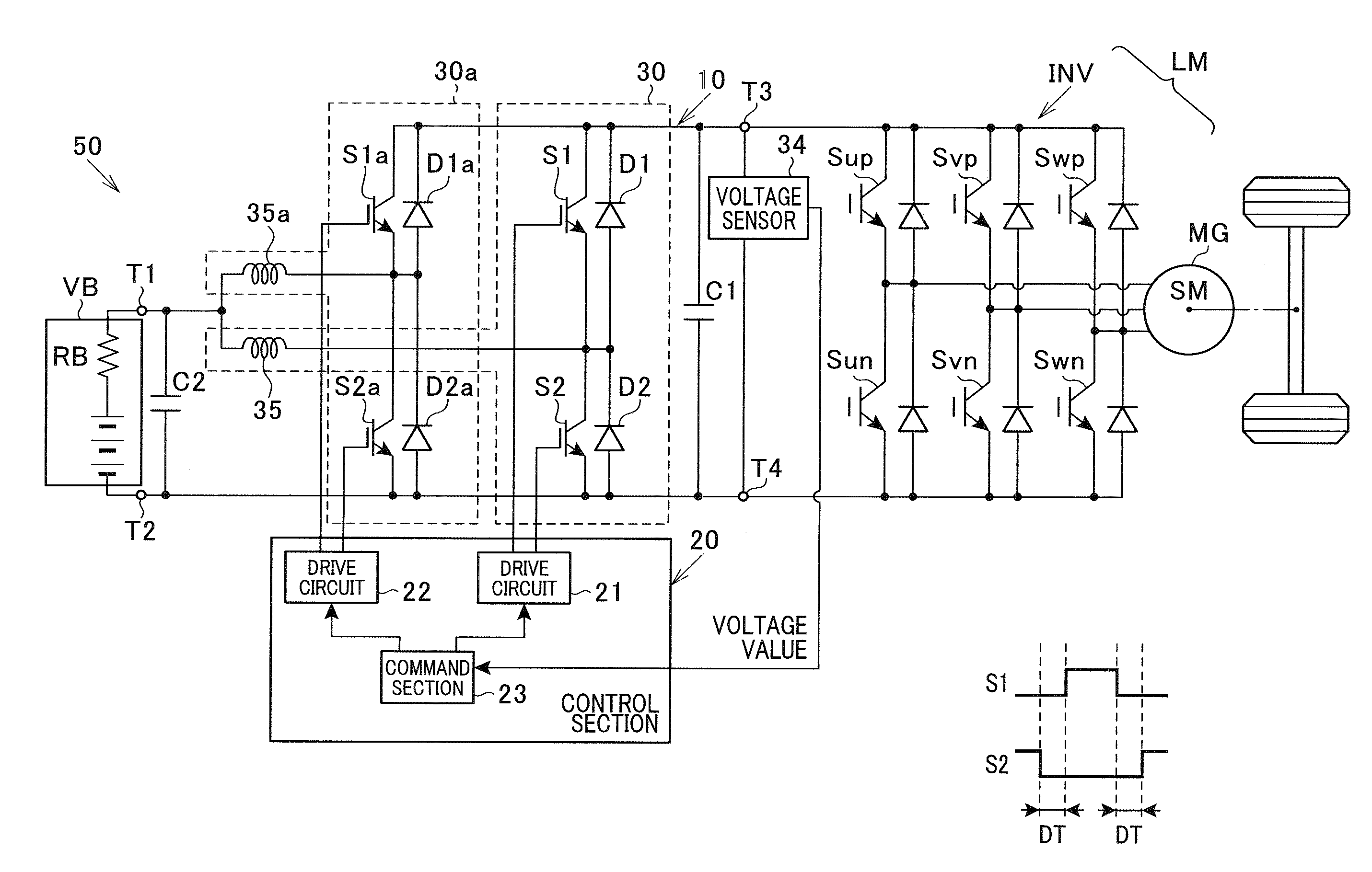
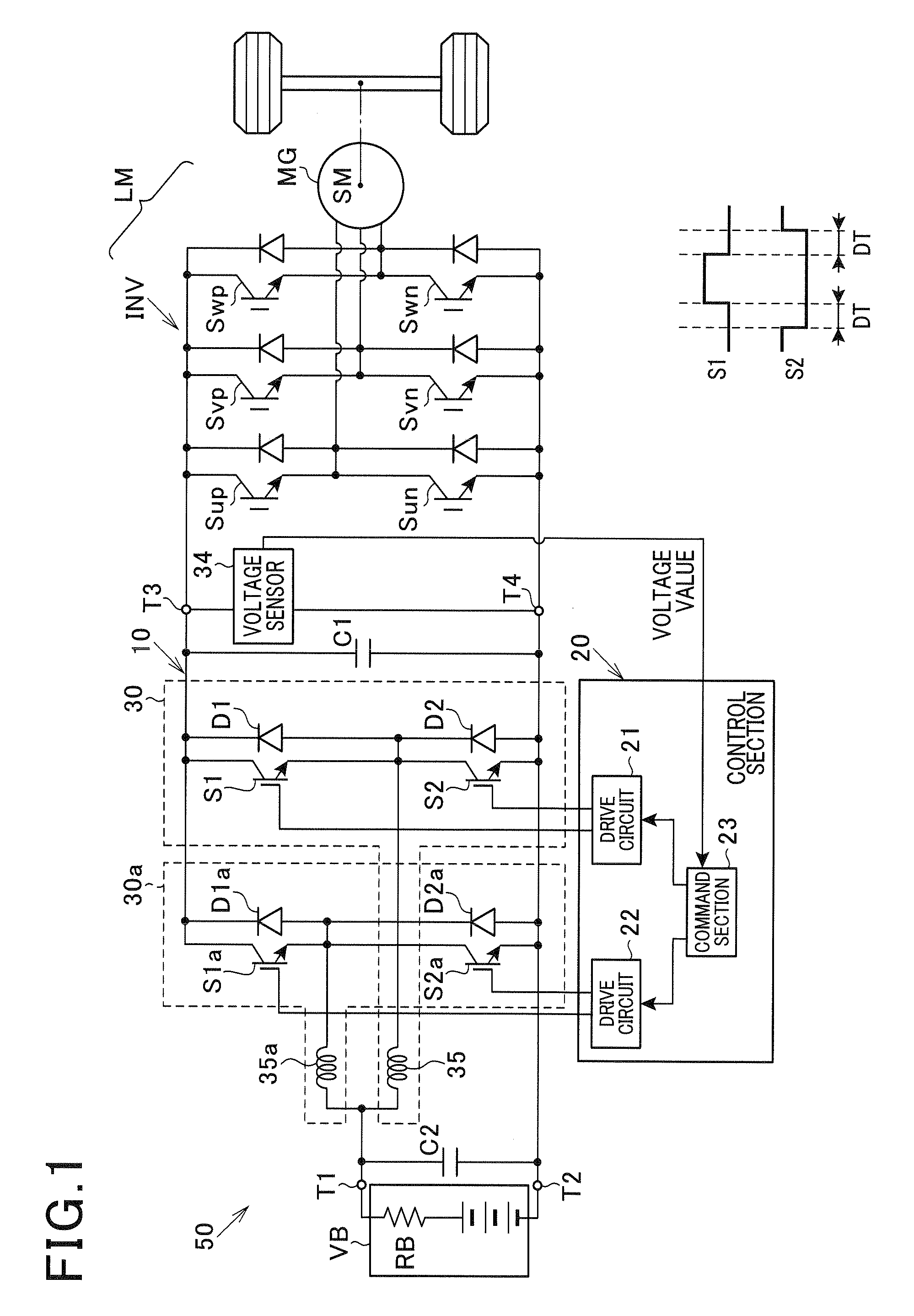
[0035]FIG. 1 is a system configuration diagram of a configuration of the power supply device 50 according to the embodiment.

[0036]The power supply device 50 supplies direct current power, i.e., DC power, to a electrical load LM that is a drive device (a three-phase alternating-current (AC) motor system, described hereafter) of a vehicle. The power supply device 50 includes a direct-current (DC) battery VB, a voltage converter 10, and a control section 20. The voltage converter 10 provides a voltage boosting function and a voltage reducing (step-down) function. In the voltage boosting function, the voltage converter 10 increases the voltage of the direct-current power supplied from the DC battery VB and applies the electrical load LM with the boosted voltage (power). In the voltage step-down ...


PUM


Abstract

A voltage converter includes a first circuit and a second circuit. The first circuit includes two or more reactors and at least one switching element. One terminal of each of the reactors is connected in parallel with respect to a power source. The at least one switching element is connected to the other terminal of each of the reactors. The second circuit includes at least one rectifier of which one terminal is connected to the electrical load. The second circuit shares with the first circuit the at least one switching element connected to the at least one rectifier. The first circuit is connected such that the power source charges the respective reactors when the at least one switching element is turned ON. The second circuit is connected such that the reactors discharge power to the electrical load when the at least one switching element is turned OFF.

Description

CROSS REFERENCE TO RELATED APPLICATION[0001]This application is based on and claims the benefit of priority from earlier Japanese Patent Application Nos. 2011-53959, 2011-53960 and 2011-286680 filed on Mar. 11, 2011, Mar. 11, 2011 and Dec. 27, 2011 respectively, the descriptions of which are incorporated herein by reference.BACKGROUND[0002]1. Technical Field[0003]The present application relates to a voltage converter and a power supply system including the voltage converter. In particular, the present application relates to technology for converting the voltage of direct-current voltage supplied from a battery and using the converted voltage to drive an electric vehicle.[0004]2. Description of the Related Art[0005]As a power supply device for electric vehicles, a power supply device is widely used that increases the voltage of a direct-current power supply, such as a battery, using a boost circuit and supplies a high voltage that is higher than the battery voltage to a drive section...

Claims


Application Information

Patent Timeline
Patent Type & Authority Patents(United States)
IPC IPC(8): H02P27/00B60L11/18B60L3/00H02M3/158B60L15/20
CPCB60L2220/14B60L2240/525Y02T10/7241B60L2240/527B60L11/1803B60L2210/40B60L2240/421H02M3/1584B60L2240/423B60L15/20Y02T10/7005B60L3/003B60L2210/30Y02T10/642Y02T10/7011H02M2001/0064Y02T10/7275B60L50/51H02M1/0064Y02T10/64Y02T10/70Y02T10/72
Inventor ITOH, TAKESHIKAKO, HIROFUMI
Owner DENSO CORP
Why Eureka
Try Eureka