Mechanical quantity sensor

a sensor and mechanical technology, applied in the direction of acceleration measurement using interia forces, turn-sensitive devices, instruments, etc., can solve the problems of sensor being incapable of normally operating as mechanical quantity sensors, abnormal oscillation, abnormal oscillation, etc., to prevent phase slope, increase the damage ratio, and reduce the change rate of acceleration detection sensitivity.

Active Publication Date: 2007-05-10
MURATA MFG CO LTD
View PDF3 Cites 9 Cited by
  • Summary
  • Abstract
  • Description
  • Claims
  • Application Information

AI Technical Summary

Benefits of technology

[0030] According to the present invention, the damping ratio is increased by connecting the resistors to the piezoelectric vibrators receiving stresses generated by a mechanical quantity in opposite directions. In this way, the range of the change rate of the acceleration detection sensitivity decreases, stabilizing the sensor with respect to temperature change. Moreover, the phase difference of the feedback voltage signal applied to both of the piezoelectric vibrators and the added signal of the currents flowing through the piezoelectric vibrators is maintained at a predetermined values and unwanted frequency components of the feedback voltage signal is suppressed. Consequently, the slope of the phase is prevented from becoming steep due to the filter circuit being provided, and the fluctuation of the detection sensitivity and the temperature change rate is reduced. Moreover, by controlling the phase, the phase of the feedback voltage signal with respect to the acceleration detection element is stabilized and the oscillation is stabilized, the noise components included in the mechanical quantity detection signal is suppressed. Accordingly, for example, the time constant of the low-pass filter for suppressing the noise components can be set at a small value, and, thus, the response can be improved.
[0031] According to the present invention, the filter circuit configured to suppress unwanted frequency components of the feedback voltage signal is a low-pass filter including the oscillation frequency in its passing band and an all-pass filter is provided at the phase control circuit configured to maintain the phase difference of the feedback voltage signal applied to both of the piezoelectric vibrators and the added signal of the current flowing through the two piezoelectric vibrators at a predetermined value. In this way, the phase can be controlled while the gain is maintained constant. Thus, stable oscillation can be maintained.
[0032] According the present invention, by the phase control circuit, the phase difference between the feedback voltage signal and the added signal is controlled so that the detection sensitivity of the mechanical quantity is maximized. Therefore, a mechanical quantity can always be detected at maximum sensitivity.

Problems solved by technology

However, when the damping ratio was increased to 6, abnormal oscillation was observed and the sensor was incapable of normally operating as a mechanical quantity sensor.
However, when the damping ratio was set at 6, the difference is 6.3 dB, causing abnormal oscillation.

Method used


Image

  • Mechanical quantity sensor
  • Mechanical quantity sensor
  • Mechanical quantity sensor

Examples


first embodiment

[0045] The structure of an acceleration sensor will be described with reference to FIGS. 1 to 6.

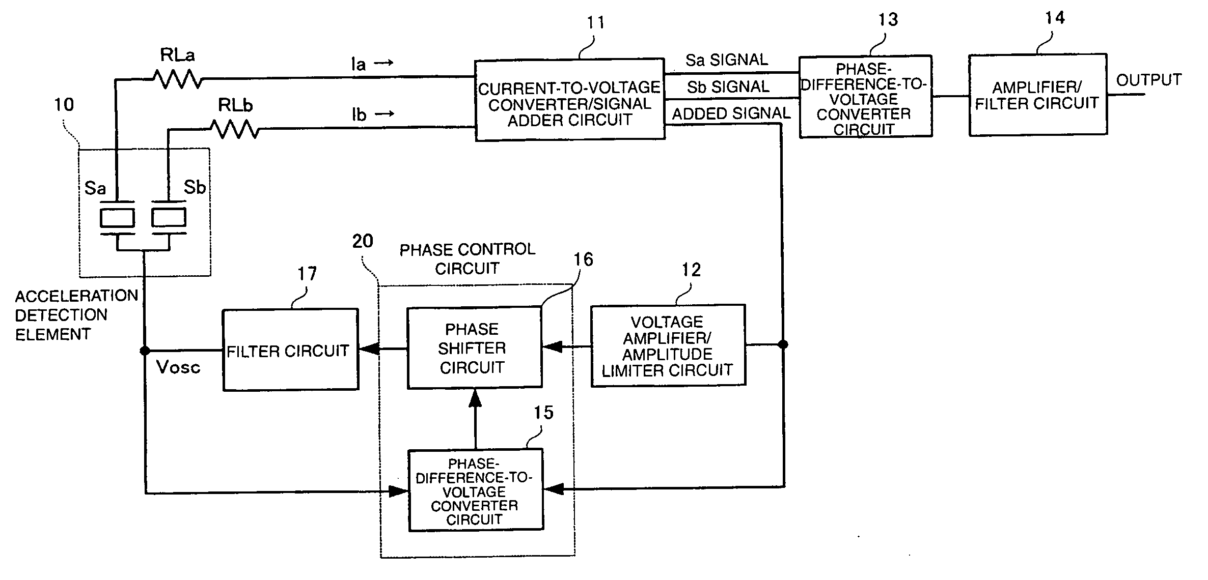
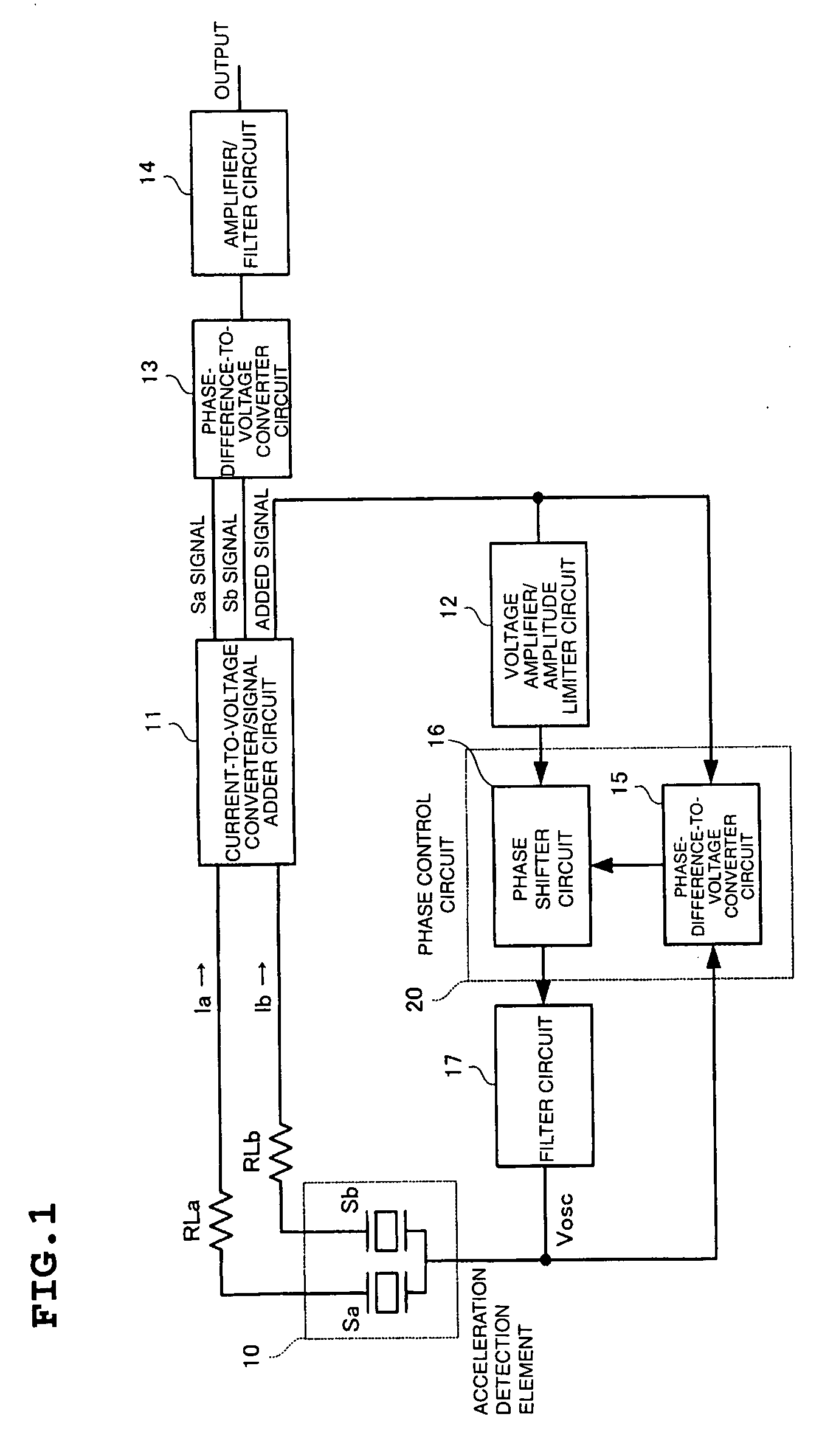
[0046]FIG. 1 is a block diagram illustrating the overall structure of the acceleration sensor. An acceleration detection element 10 includes piezoelectric vibrators Sa and Sb receiving stresses generated by acceleration applied in opposite directions. A current-to-voltage converter / signal adder circuit 11 converts the current signals flowing through the piezoelectric vibrators Sa and Sb of the acceleration detection element 10 into voltage signals and outputs Sa and Sb signals. The current-to-voltage converter / signal adder circuit 11 also outputs an added signal obtained by adding the Sa and Sb signals.

[0047] A voltage amplifier / amplitude limiter circuit 12 amplifies the voltage of the added signal and limits its amplitude.

[0048] A phase control circuit 20 controls the phase of the output signal from the voltage amplifier / amplitude limiter circuit 12. A filter circuit 17 attenuates out...

second embodiment

[0071] Next, an acceleration sensor will be described with reference to FIG. 7.

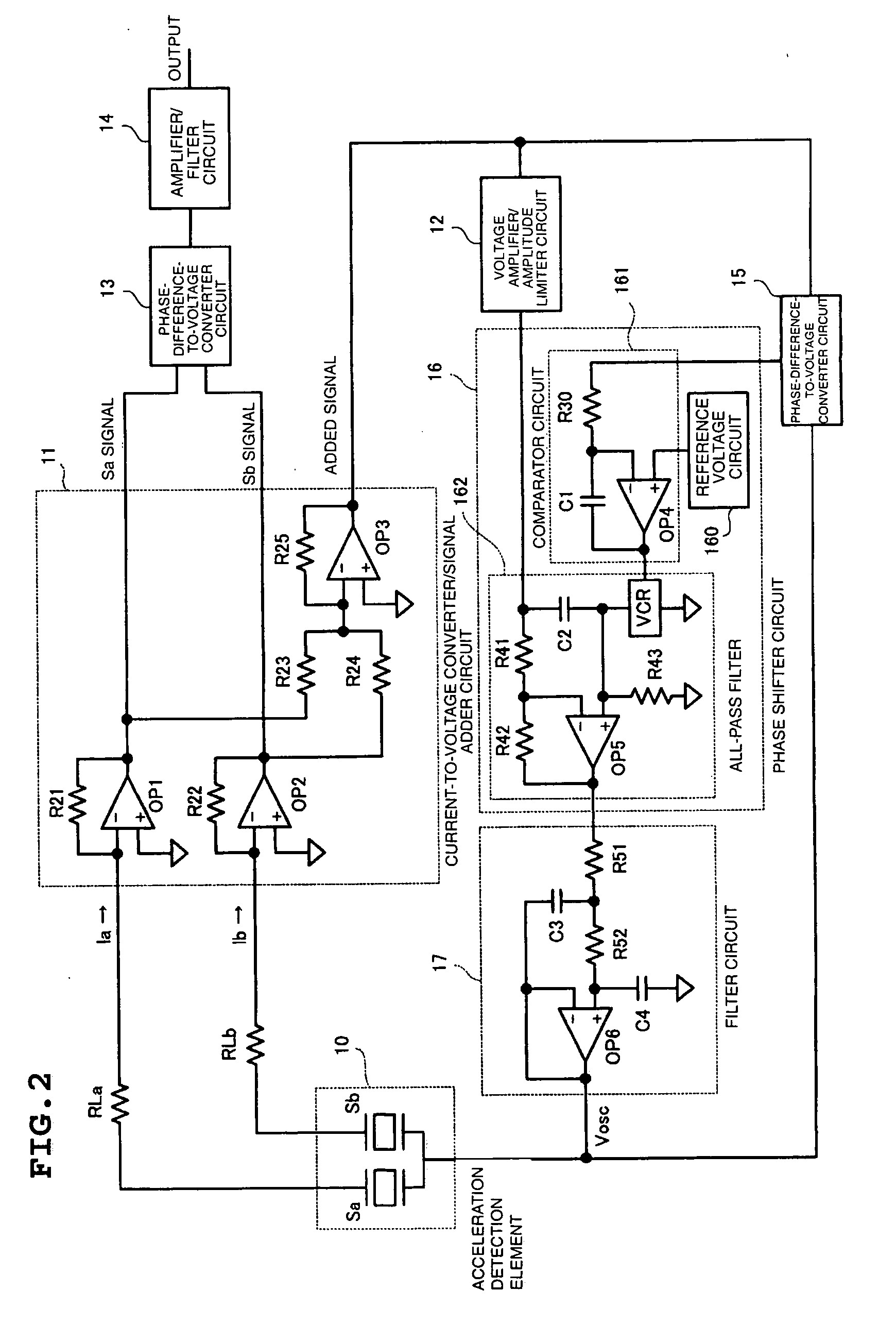
[0072] The structure of the current-to-voltage converter / signal adder circuit 11 of the acceleration sensor according to the second embodiment differs from that of the sensor shown in FIG. 2. The structure of the current-to-voltage converter / signal adder circuit 11 according to the second embodiment adds voltages generated in resistors RLa and RLb when electric currents Ia and Ib flowing through piezoelectric vibrators Sa and Sb, respectively, of the acceleration detection element 10 flow through resistors RLa and RLb respectively. Operational amplifier OP1 and OP2 each have significantly high input impedance and constitute a voltage follower circuit the gain of that is 1. An operational amplifier OP3 and resistors R25 and R26 constitute a noninverting amplifier circuit. The noninverting amplifier circuit and resistors R23 and R24 constitute an adder circuit that receives an added signal generated from t...


PUM

PropertyMeasurementUnit
temperatureaaaaaaaaaa
damping ratioaaaaaaaaaa

Abstract

A mechanical quantity sensor includes a current-to-voltage converter/signal adder circuit that converts electric current signals flowing through two piezoelectric vibrators into voltage signals. The piezoelectric vibrators receive stresses generated by a mechanical quantity, such as acceleration, in opposite directions. A voltage amplifier/amplitude limiter circuit amplifies an added signal obtained from the two voltage signals and limits its amplitude. A phase-difference-to-voltage converter circuit detects a difference in the phases of the added signal and a feedback voltage signal applied to an acceleration detection element. A phase shifter circuit controls the phase of the feedback voltage signal so that the phase is a predetermined phase. A filter circuit minimizes frequency components higher than an oscillation frequency in an unwanted frequency band. By increasing the resistance of resistors so as to increase the damping ratio, temperature stability is increased. Accordingly, abnormal oscillation is prevented by the filter circuit, and fluctuation in the characteristics is minimized by the phase control circuit.

Description

TECHNICAL FIELD [0001] The present invention relates to a mechanical quantity sensor configured to detect a mechanical quantity such as acceleration, angular acceleration, angular velocity, or load. BACKGROUND ART [0002] A known acceleration sensor including piezoelectric vibrators is disclosed in Patent Document 1 filed by the assignee / applicant of this application. [0003] The known acceleration sensor outputs an acceleration detection signal in the following manner. A bridge circuit is configured with two piezoelectric vibrators receiving stresses generated by acceleration in opposite directions and two load impedances each including a capacitor. A voltage-dividing impedance circuit is provided between the average output terminals of the bridge circuit. An oscillating circuit is configured by feeding back a signal from the voltage-dividing point of the voltage-dividing impedance circuit to the connection point of the two piezoelectric vibrators by a feedback signal processing circ...

Claims


Application Information

Patent Timeline
Patent Type & Authority Applications(United States)
IPC IPC(8): H01L41/08G01C19/56G01C19/5776G01L1/16G01P15/09G01P15/097G01P15/10
CPCG01P15/09G01P15/097
Inventor YAMASHITA, MUNEHARU
Owner MURATA MFG CO LTD
Why Eureka
Try Eureka