Rotary vibrating table and system

A technology of turntable and shaking table, applied in vibration testing, measuring devices, instruments, etc., can solve the problems of high minimum measurement frequency, low bearing capacity, and high price of shaking table, and achieve low minimum measurement frequency, high bearing capacity, simple structure

Active Publication Date: 2017-05-10
INST OF ENG MECHANICS CHINA EARTHQUAKE ADMINISTRATION
View PDF8 Cites 8 Cited by
  • Summary
  • Abstract
  • Description
  • Claims
  • Application Information

AI Technical Summary

Problems solved by technology

[0004] The purpose of the present invention is to provide a rotating vibrating table to solve the technical problems of high price, high minimum measurement frequency and small bearing capacity of the existing vibrating table in the prior art
[0005] The purpose of the present invention is also to provide a rotational vibration system to solve the technical problems of high price, high minimum measurement frequency and small bearing capacity of the vibration table in the prior art

Method used


Image

  • Rotary vibrating table and system
  • Rotary vibrating table and system
  • Rotary vibrating table and system

Examples


Embodiment 1

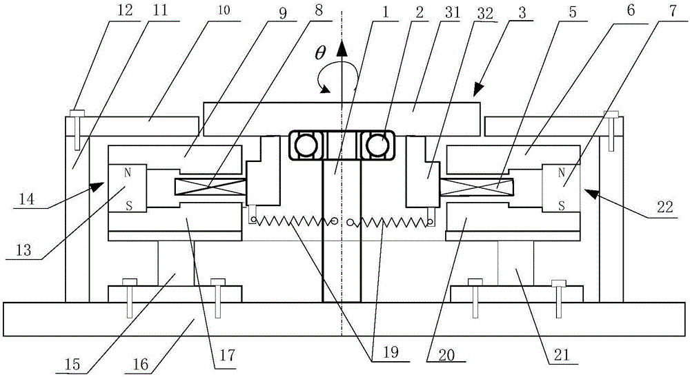
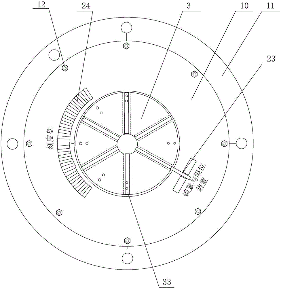
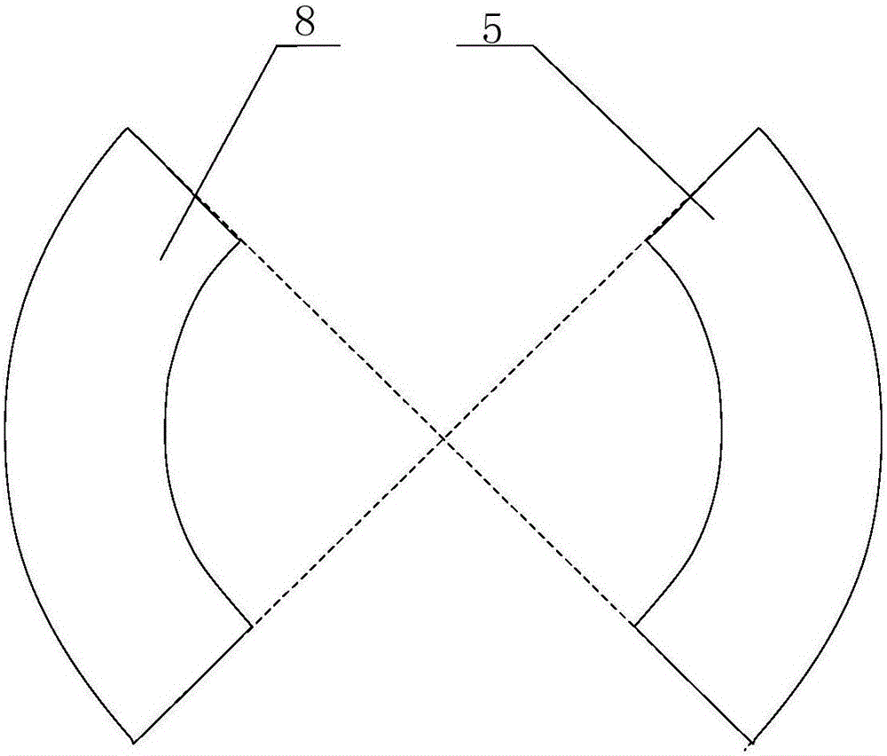
[0045]see Figure 1-Figure 8 As shown, the present embodiment provides a rotary vibrating table; figure 1 The first angle sectional view of the rotary vibrating table provided for this embodiment (the hatching is not shown in the figure); figure 2 Schematic diagram of the second angle structure of the rotary vibrating table provided in this embodiment; image 3 Schematic diagram of the structure of the drive coil and feedback coil of the rotary vibrating table provided in this embodiment; Figure 4 Schematic diagram of the structure of the driving permanent magnet and the feedback permanent magnet of the rotary vibrating table provided in this embodiment; Figure 5 Schematic diagram of the structure of the drive magnetic circuit and the feedback magnetic circuit of the rotary vibrating table provided in this embodiment; Figure 6 A cross-sectional view of the drive coil or feedback coil of the rotary vibrating table provided in this embodiment (only the label of the drive ...


PUM


Abstract

The invention relates to the technical field of measurement calibrating equipment, in particular to a rotary vibrating table and system; the rotary vibrating table comprises a base, a support shaft and a rotary table; the base is connected with the rotary table through the support shaft, and the rotary table may rotate around the support shaft relative to the base; a driving coil and a feedback coil are disposed between the base and the rotary table; the driving coil and the feedback coil are disposed on two sides of the support shaft and are fixedly connected respectively to the rotary table; a drive magnetic circuit and a feedback magnetic circuit are fixedly connected to the base; the driving coil may rotate in reciprocating manner around the axis of the support shaft in the drive magnetic circuit, and the feedback coil may rotate in reciprocating manner around the axis of the support shaft in the feedback magnetic circuit. The rotary vibrating system comprises the rotary vibrating table. The invention is intended to provide the rotary vibrating table and system in order to solve the technical problem of the prior art that the vibrating table has high price, relatively high lowest measurement frequency and low bearing capacity.

Description

technical field [0001] The invention relates to the technical field of measuring and calibrating equipment, in particular to a rotating vibrating table and a system thereof. Background technique [0002] At present, there are angular vibration vibrating tables driven by torque motors at home and abroad. The measurement principle is generally calibrated once by laser interferometry, and the frequency range is 5Hz-500Hz; but the vibrating table is expensive and the minimum measurement frequency is high. In addition, the bearing capacity of the current angular vibration table is generally less than 10kg, which can only be used for the calibration of general angular vibration sensors, and cannot be used for the calibration of larger seismic rotation sensors and the anti-torsional vibration test of small-scale structures. [0003] Therefore, there is an urgent need for a relatively low-cost, low-minimum measurement frequency, and high-capacity rotational vibration table and its s...

Claims


Application Information

Patent Timeline
Patent Type & Authority Applications(China)
IPC IPC(8): G01M7/02G01V13/00
CPCG01M7/02G01V13/00
Inventor 高峰杨学山车晓军王雷杨巧玉尚帅锟贾行建
Owner INST OF ENG MECHANICS CHINA EARTHQUAKE ADMINISTRATION
Why Eureka
Try Eureka