Swing analyzer and golf club shaft selecting system

a golf club shaft and analyzer technology, applied in golfing accessories, instruments, gymnastics, etc., can solve the problems of difficult to select a suitable golf club shaft for each golfer, and it is impossible with a simple structure to analyze the swing characteristics of users, and achieve the effect of simple structur

Active Publication Date: 2014-11-18
MIZUNO CORPORATION
View PDF16 Cites 46 Cited by
  • Summary
  • Abstract
  • Description
  • Claims
  • Application Information

AI Technical Summary

Benefits of technology

[0013]The present invention was made in view of the foregoing, and its object is to provide a swing analyzer and a golf club shaft selecting system that can analyze swing characteristics of a user and select kick point suitable for the swing characteristics of the user, with a simple structure.
[0019]By the swing analyzer and the golf club shaft selecting system in accordance with the present invention, a shaft suitable for the swing characteristics of the user can be selected, and the device and system structures can be simplified.

Problems solved by technology

This makes it very difficult to select a suitable golf club shaft for each golfer.
It is impossible with a simple structure to analyze swing characteristics of a user and to select kick point suitable for the swing characteristics of the user.

Method used


Image

  • Swing analyzer and golf club shaft selecting system
  • Swing analyzer and golf club shaft selecting system
  • Swing analyzer and golf club shaft selecting system

Examples


first embodiment

[0040][First Embodiment]

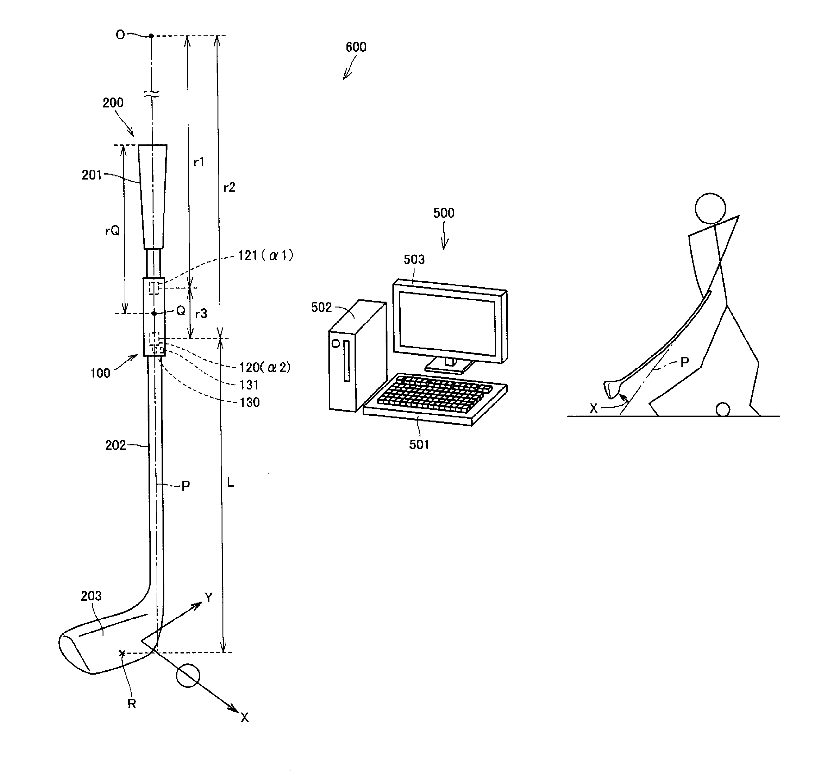
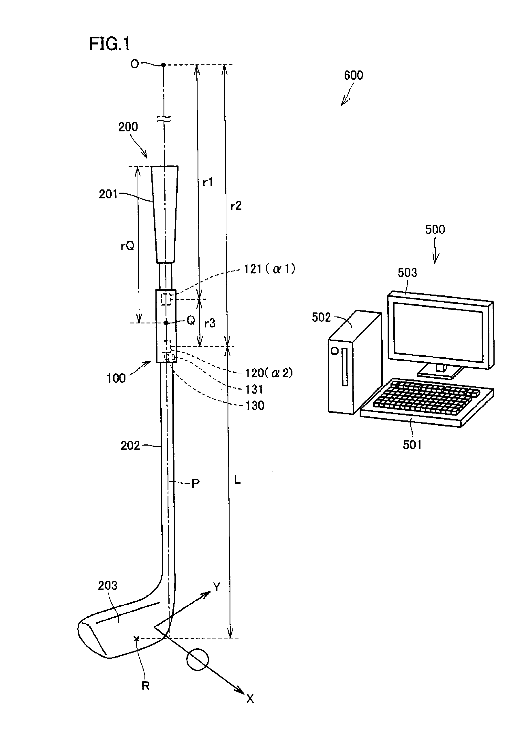
[0041]FIG. 1 is an illustration showing schematic structure of the golf club selecting system 600. As shown in FIG. 1, golf club selecting system 600 includes a measuring device (swing measuring device) 100 attached to a golf club 200, and an external support device 500 provided separate from measuring device 100.

[0042]Golf club 200 includes a shaft 202, a head 203 provided at one end of shaft 202, and a grip 201 provided at the other end of shaft 202.

[0043]External support device 500 includes an external processing unit 502, an external display unit 503 displaying a result of calculation by external processing unit 502, and an external input unit 501 allowing input of data and the like to external processing unit 502.

[0044]Measuring device 100 calculates “head speed” immediately before impact, “swing tempo” representing maximum amount of deflection during a swing, “kick angle” immediately before impact, “toe down amount” immediately before impact, “deflectio...

second embodiment

[0139](Second Embodiment)

[0140]A golf club shaft selecting system in accordance with a second embodiment will be described with reference to FIG. 18.

[0141]FIG. 18 is a graph showing a relation between cock angle and radius of rotation of the shaft immediately before impact. The cock angle refers to an angle formed by golf club 200 and the user's arm, at the wrist portion of the user.

[0142]Using an image pick-up device or the like, the cock angle immediately before impact when the user hits the ball is measured. The radius R of rotation of the shaft immediately before impact can be calculated from the head speed calculated by measuring device 100 and Equations (4) and (5) above. Sampled results are as plotted in FIG. 18.

[0143]When we represent the cock angle by y and the radius of rotation of shaft immediately before impact by x, the following approximation is possible: y=grip 201.57x−102.13:R2 (coefficient of determination, square of correlation)=0.8648.

[0144]Therefore, it is possib...


PUM

PropertyMeasurementUnit
timeaaaaaaaaaa
timeaaaaaaaaaa
timeaaaaaaaaaa

Abstract

A measuring device includes a strain gauge, a processing unit calculating an expected bending point value corresponding to a bending point position, and a display unit capable of displaying an output value from the processing unit. The processing unit calculates the expected bending point value based on a measured value of strain gauge at a first time point during a swing of the user and a measured value of strain gauge at a second time point closer to an impact time point than the first time point. The processing unit stores in advance conversion data for converting the expected bending point value to recommended kick point output value indicating kick point, and the processing unit outputs the recommended kick point output value corresponding to the calculated expected bending point value to the display unit.

Description

[0001]This nonprovisional application is based on Japanese Patent Application No. 2009-032805 filed with the Japan Patent Office on Feb. 16, 2009, the entire contents of which are hereby incorporated by reference.BACKGROUND OF THE INVENTION[0002]1. Field of the Invention[0003]The present invention relates to a swing analyzer and a golf club shaft selecting system. More specifically, the present invention relates to a swing analyzer and a golf club shaft selecting system that support selection of a kick point suitable for a user.[0004]2. Description of the Background Art[0005]A golf club shaft has various characteristics, and it is necessary for a golfer to select a golf club shaft having characteristics suitable for the golfer. A golf club shaft suitable for each golfer can be selected in most cases by appropriately selecting shaft mass, flex and kick point, among various characteristics of a golf club shaft. The shaft mass, flex and kick point, however can be designed independent f...

Claims


Application Information

Patent Timeline
Patent Type & Authority Patents(United States)
IPC IPC(8): A63B59/00A63B24/00A63B69/36G01N3/00
CPCA63B2059/0003A63B2024/0034A63B2220/30A63B2220/51A63B2220/16A63B2220/40A63B59/0074A63B2220/807A63B2220/806A63B2024/0028A63B2225/50A63B60/42A63B60/002
Inventor SATO, FUMINOBUNAGAO, HIROSHIKIMURA, TAKASHI
Owner MIZUNO CORPORATION
Why Eureka
Try Eureka