
Body-worn monitor for measuring respiratory rate

a technology of respiratory rate and body, applied in the field of medical devices for monitoring vital signs, to achieve the effect of reducing false alarms, accurate measurement of respiratory rate, and improving true positive alarms

Active Publication Date: 2014-11-18
SOTERA WIRELESS
View PDF479 Cites 41 Cited by
  • Summary
  • Abstract
  • Description
  • Claims
  • Application Information

AI Technical Summary

Benefits of technology

This patent describes a way to measure heart rate using a body-worn device that collects data from an accelerometer and a pulse sensor. The device analyzes these data using algorithms to determine the patient's heart rate based on their motion level. This allows for accurate measurement of heart rate during different levels of activity. The algorithms are performed using a microprocessor located in either the wrist-worn device or a server in a hospital, and the results are sent to the wrist-worn device for final processing. This distributed model reduces computational load and conserves power, which extends battery life. The accelerometer is placed on the patient's torso to measure the small movements caused by breathing, which are highly sensitive to their motion and position. This allows for accurate measurement of heart rate and filtering out of motion noise from the pulse sensor data. Overall, this technique provides a non-invasive and accurate way to measure heart rate.

Problems solved by technology

Perhaps more importantly, with a conventional monitoring device a walking patient may yield a noisy IP signal that is then processed to determine an artificially high RR, which then triggers a false alarm.

Method used


Image

  • Body-worn monitor for measuring respiratory rate
  • Body-worn monitor for measuring respiratory rate
  • Body-worn monitor for measuring respiratory rate

Examples


Embodiment Construction

[0070]Sensor Configuration

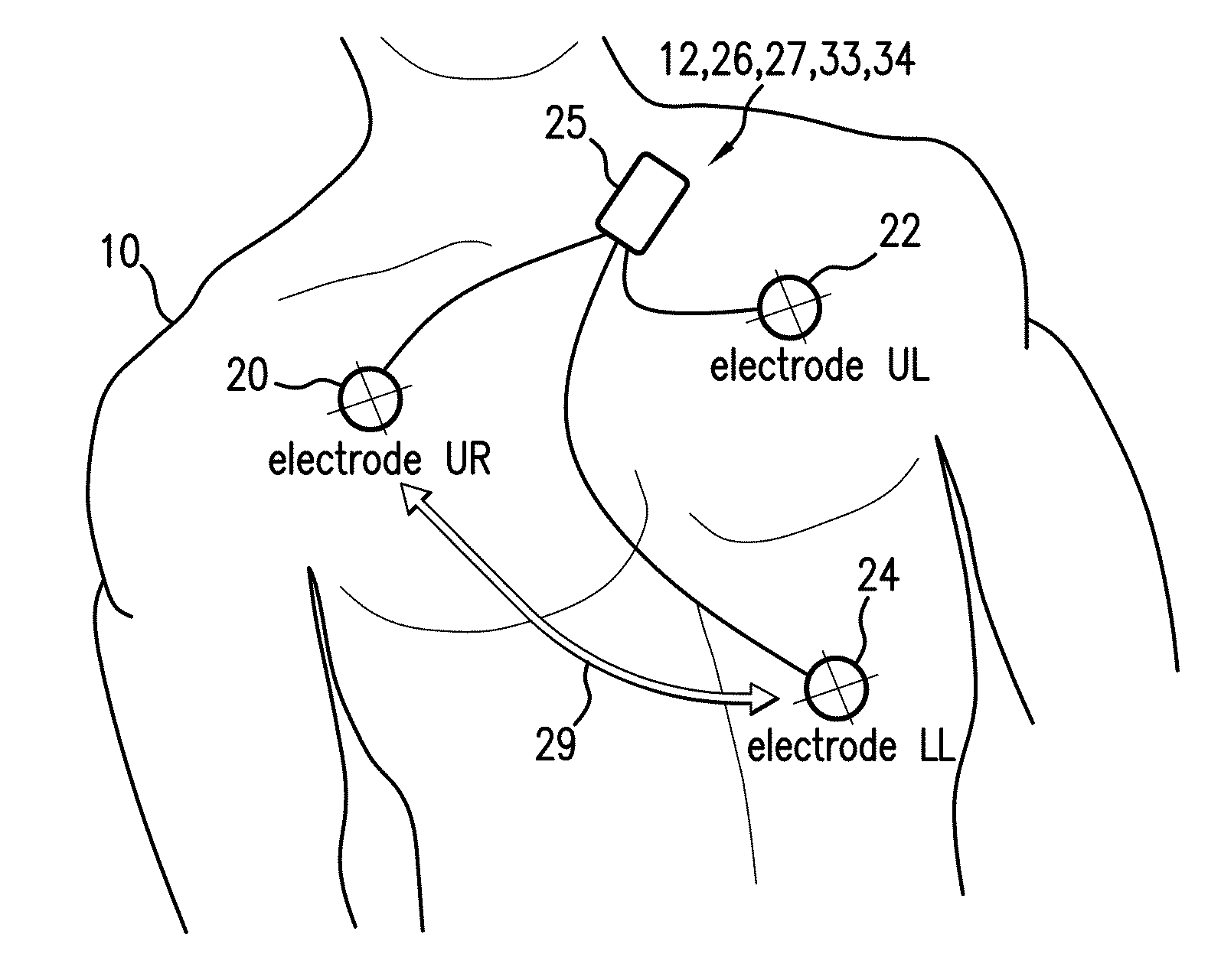
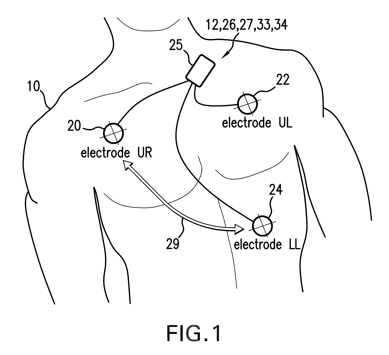
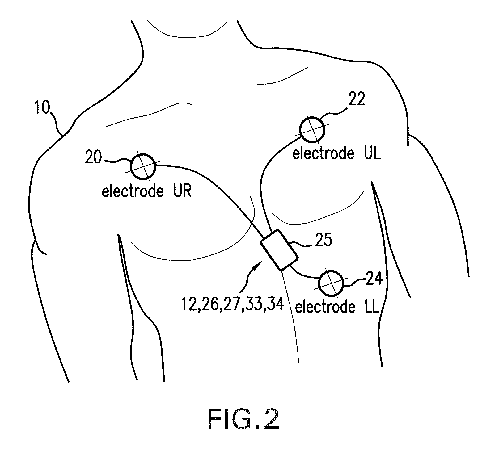
[0071]Referring to FIGS. 1 and 2, a sensor module 25 featuring an IP circuit 27 and accelerometer 12 is mounted on the chest of a patient 10 to simultaneously measure IP and ACC waveforms. A multi-component algorithm, featuring specific algorithms based on simple peak counting, FFT analysis, and adaptive filters processes these waveforms to accurately measure RR even when the patient 10 is moving. During a measurement, both the IP 27 and an ECG circuit 26 within the sensor module connect to a trio of electrodes 20, 22, 24 typically positioned on the patient's torso in an Einthoven's triangle configuration. Each electrode 20, 22, 24 measures a unique analog signal that passes through a shielded cable to the ECG circuit 26. This component typically includes a differential amplifier and a series of analog filters with passbands that pass the high and low-frequency components that contribute to the ECG waveform, but filter out components associated with electri...


PUM


Abstract

The invention provides a system for measuring respiratory rate (RR) from a patient. The system includes an impedance pneumography (IP) sensor, connected to at least two electrodes, and a processing system that receives and processes signals from the electrodes to measure an IP signal. A motion sensor (e.g. an accelerometer) measures at least one motion signal (e.g. an ACC waveform) describing movement of a portion of the patient's body to which it is attached. The processing system receives the IP and motion signals, and processes them to determine, respectfully, frequency-domain IP and motion spectra. Both spectra are then collectively processed to remove motion components from the IP spectrum and determine RR. For example, during the processing, an algorithm determines motion frequency components from the frequency-domain motion spectrum, and then using a digital filter removes these, or parameters calculated therefrom, from the IP spectrum.

Description

BACKGROUND OF THE INVENTION[0001]1. Field of the Invention[0002]The present invention relates to medical devices for monitoring vital signs, e.g., respiratory rate (RR).[0003]2. Description of the Related Art[0004]RR is a vital sign typically measured in hospitals using either an indirect, electrode-based technique called ‘impedance pneumography’ (IP), a direct optical technique called ‘end-tidal CO2’ (et-CO2), or simply through manual counting of breaths by a medical professional. IP is typically performed in lower-acuity areas of the hospital, and uses the same electrodes which measure an electrocardiogram (ECG) and corresponding heart rate (HR). These electrodes are typically deployed in a conventional ‘Einthoven's triangle’ configuration on the patient's torso. During IP, one of the electrodes supplies a low-amperage (˜4 mA) current that is typically modulated at a high frequency (˜50-100 kHz). Current passes through the patient's thoracic cavity, which is characterized by a var...

Claims


Application Information

Patent Timeline
Patent Type & Authority Patents(United States)
IPC IPC(8): A61B5/08A61B5/11A61B5/00
CPCA61B2562/0219A61B5/7257A61B5/6801A61B5/7239A61B5/0809A61B5/11
Inventor BANET, MATTDHILLON, MARSHALMCCOMBIE, DEVIN
Owner SOTERA WIRELESS
Learn More