Flue gas purification system with different nozzles

Inactive Publication Date: 2014-11-18
HAMON ENVIROSERV GMBH
View PDF20 Cites 1 Cited by
  • Summary
  • Abstract
  • Description
  • Claims
  • Application Information

AI Technical Summary

Benefits of technology

[0015]The invention provides an option for realizing optimizations of a flue gas purification system with manageable financial expenditures, wherein said optimizations make it possible to also us

Problems solved by technology

In large systems with, for example, volumetric flue gas flows greater than 2,000,000 Nm3/h, it is furthermore necessary to operate two o

Method used


Image

  • Flue gas purification system with different nozzles
  • Flue gas purification system with different nozzles
  • Flue gas purification system with different nozzles

Examples


Example

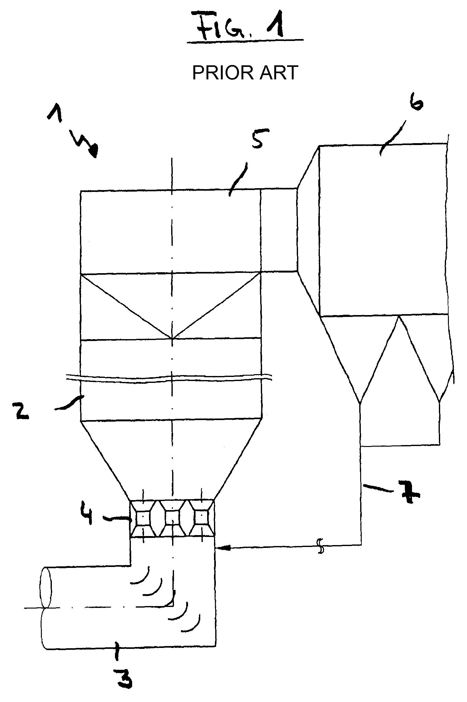
[0021]In the flue gas purification system 1 according to the prior art shown in FIG. 1, a fluidized bed reactor 2 is charged with flue gas. This flue gas is introduced into the fluidized bed reactor 2 from a boiler via a line 3 and nozzles 4. The flue gas to be purified flows through a sorbent placed into the fluidized bed reactor. A circulating fluidized bed forms in dependence on the flow speeds and the introduced particle sizes. The reaction between the flue gas or the noxious matter contained therein and the sorbent takes place in the fluidized bed. An outlet unit 5, through which the flue gas / sorbent mixture is transferred from the fluidized bed reactor 2 into a filter unit 6, is situated on the upper end of the fluidized bed reactor 2 referred to the flow direction of the flue gas to be purified. The filter unit 6 contains, for example, bag filters or electric filters or combinations thereof. Sorbent fractions filtered out of the flue gas can be returned into the reactor 2 via...


PUM

PropertyMeasurementUnit
Dynamic viscosityaaaaaaaaaa

Abstract

The aim of the invention is to devise a flue gas purification system which allows the use of only one absorber even for large systems. The flue gas purification system according to the invention comprises a fluidized-bed reactor having a flue gas inlet unit and a flue gas outlet unit, a nozzle unit being mounted downstream of the flue gas inlet unit. Said nozzle unit is provided with nozzles, said nozzles having different cross-sections.

Description

BACKGROUND OF THE INVENTION[0001]The present invention pertains to a flue gas purification system with a fluidized bed reactor that features a flue gas inlet unit and a flue gas outlet unit.[0002]Flue gas purification systems are extensively known from the prior art. A system of this type is described, for example, in WO 2006 / 032288 A1. Such systems are used for carrying out methods for the separation of noxious gases such as, for example, HCl, HF or SO2. Dioxins, furanes and heavy metals such as, for example, mercury can also be effectively separated if so-called sorbents such as hearth-type furnace coke, activated carbon or the like is also added. Fluidized bed reactors, into which the flue gas to be purified is introduced via a flue gas inlet unit, may be used for carrying out this method. This unit usually consists of a pipeline that arrives from the boiler and features one or more outlets into the reactor area. A sorbent is placed or introduced into the reactor. A fluidized bed...

Claims


Application Information

Patent Timeline
IPC IPC(8): B01D53/12B01D53/83B01D53/50B01D53/00
CPCB01D53/83F23J2219/60B01D53/508
Inventor FELDKAMP, MARKUSBAEGE, RUDIGERDICKAMP, MARKUSRISSE, THEOMOSER, CHRISTIAN
Owner HAMON ENVIROSERV GMBH
Why Eureka
Try Eureka