Alternating current/direct current two-way switch

a two-way switch and direct current technology, applied in the direction of substation/switching arrangement details, pulse technique, power conversion systems, etc., can solve the problems of affecting the function of the switch, affecting the service life of the switch, so as to achieve the effect of convenient connection

Active Publication Date: 2014-11-18
PANASONIC CORP
View PDF26 Cites 26 Cited by
  • Summary
  • Abstract
  • Description
  • Claims
  • Application Information

AI Technical Summary

Benefits of technology

[0008]In view of the above, the present invention provides an AC / DC two-way switch capable of being employed in an AC distribution system as well as a DC distribution system; particularly, switching without generating an arc when used in the DC distribution system, and easily substituting for an existing AC distribution system.

Problems solved by technology

Thus, it is not easy to substitute a switch for the existing AC distribution system with a switch for a DC distribution system or combine the switch for the DC distribution system with the switch for the existing AC distribution system.
Furthermore, the presence of switches each having a different size degrades aesthetical appearance and is not desirable in terms of interior design.
Further, when a polarity is erroneously connected between the DC power and the switch, the current flows by way of a diode included in the MOSFET unit, and, accordingly, the MOSFET does not serve as a switch.
In this case, the MOSFET operates only in either one of the directions of the currents, which makes function as a switch incomplete.
In other words, the DC switch cannot be employed in the AC power system in which the flow direction of current is inverted every half period.

Method used


Image

  • Alternating current/direct current two-way switch
  • Alternating current/direct current two-way switch
  • Alternating current/direct current two-way switch

Examples


Embodiment Construction

[0057]Hereinafter, embodiments of the present invention will be described in more detail with reference to accompanying drawings which form a part hereof.

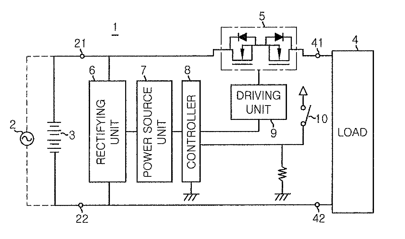
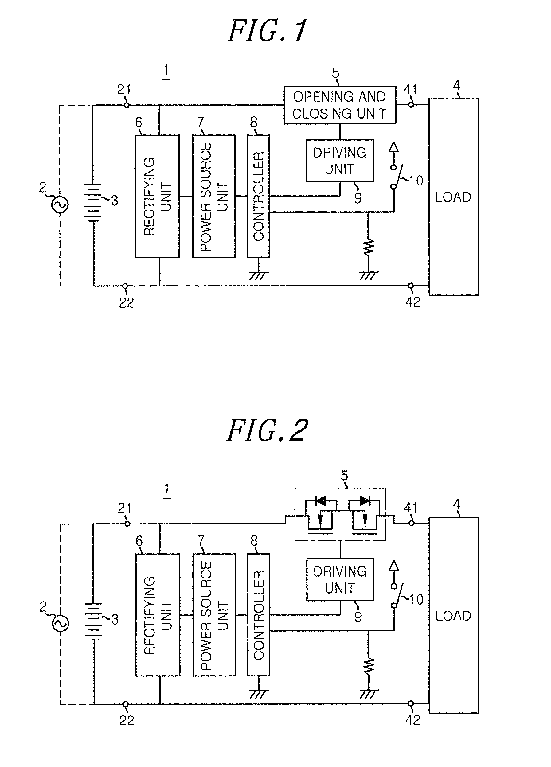
[0058]An AC / DC two-way switch in accordance with an embodiment of the present invention will be described with reference to the accompanying drawings. FIG. 1 is a block diagram showing a basic configuration of an AC / DC two-way switch 1 in accordance with an embodiment of the present invention.

[0059]Referring to FIG. 1, the AC / DC two-way switch 1 is connected between one of an AC power source 2 and a DC power source 3 and a load 4. The AC / DC two-way switch 1 includes an opening and closing unit 5 having a bi-directional semiconductor switch connected in series between a first input terminal 21 to which one side of the AC power source 2 or a positive electrode side of the DC power source 3 is connected and a first output terminal 41 to which one end of the load 4 is connected, and a rectifying unit 6 connected between the first input...


PUM


Abstract

There is provided an AC / DC two-way switch connected between an AC power source or a DC power source and a load to control a power supply to the load. The AC / DC two-way switch includes: a bi-directional semiconductor switch element having a transistor structure connected in series between a power source and the load; a rectifying unit connected in parallel between the first input terminal and a second input terminal; a power source unit for converting an output voltage from the rectifying unit into a stable voltage; and a controller for controlling an entire operation of the AC / DC two-way switch. The AC / DC two-way switch further includes a driving unit for turning on the bi-directional semiconductor switch element in response to a control signal.

Description

[0001]This application is a Continuation Application of PCT International Application No. PCT / IB2010 / 001417 filed on Jun. 14, 2010, which designated the United States.FIELD OF THE INVENTION[0002]The present invention relates to an alternating current / direct current (AC / DC) two-way switch usable for both AC and DC that supplies an AC or DC power to a load therethrough and stops supplying of power.BACKGROUND OF THE INVENTION[0003]Conventionally, an AC distribution system based on a commercial power has been used to supply power to various electric devices in a house. Recently, there becomes widely used a DC decentralized power supply system using a solar cell (photovoltaic power generation), a fuel cell, a storage battery, or the like provided in the house. Also, in order to reduce a power loss in converting an AC power into a DC power in each electronic device, there is proposed an introduction of a home DC distribution system. In these cases, a DC distribution system is required to ...

Claims


Application Information

Patent Timeline
Patent Type & Authority Patents(United States)
IPC IPC(8): H03K17/687H03K17/691H03K17/16H02M1/08
CPCH02M1/083H03K2217/0009H03K17/162H03K17/6874H02M1/08H03K17/6871H03K17/691Y10T307/845H03K17/133H03K2017/6878H03K2217/0081H02M1/10
Inventor GOTOU, KIYOSHI
Owner PANASONIC CORP
Why Eureka
Try Eureka