

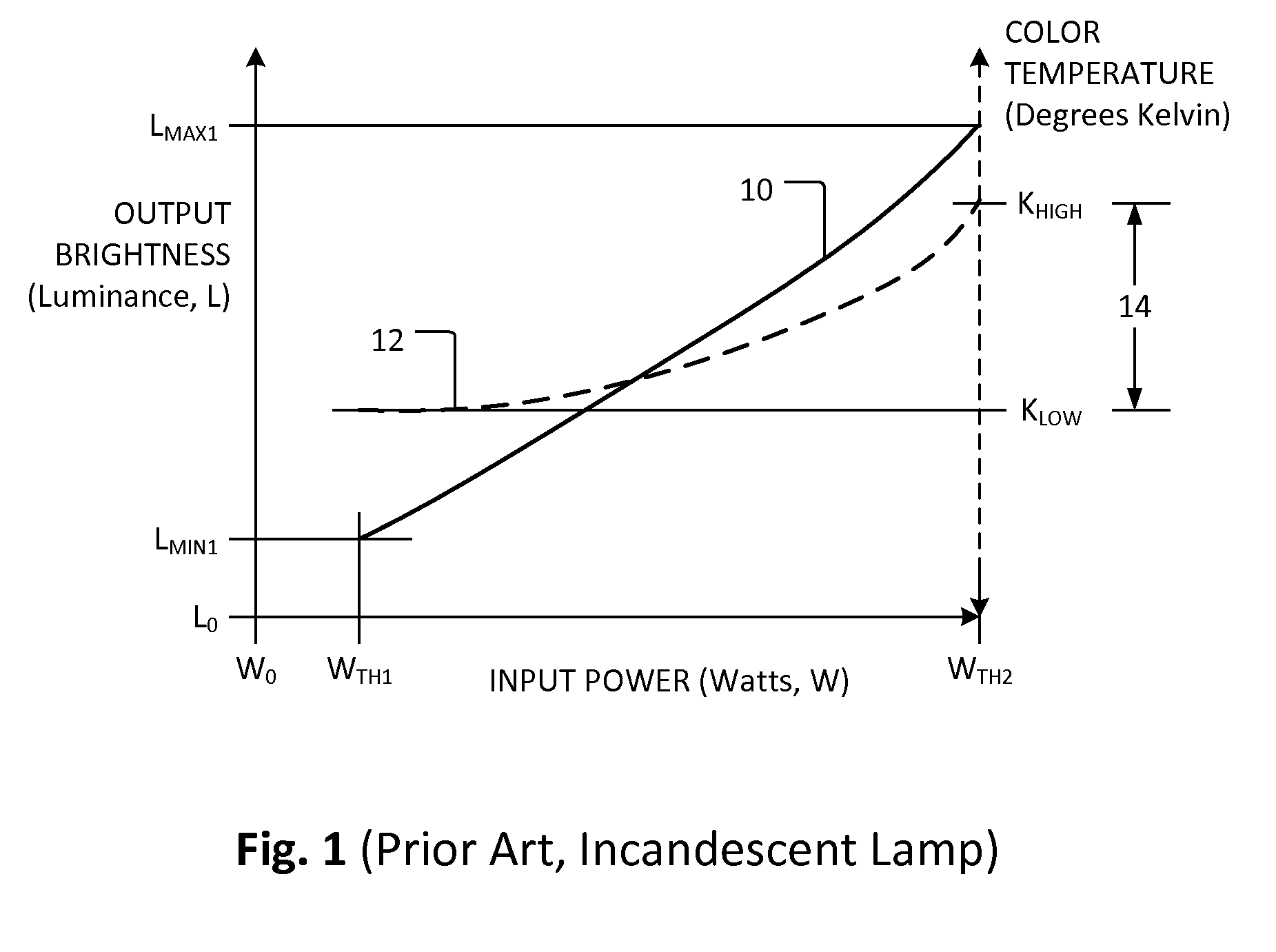
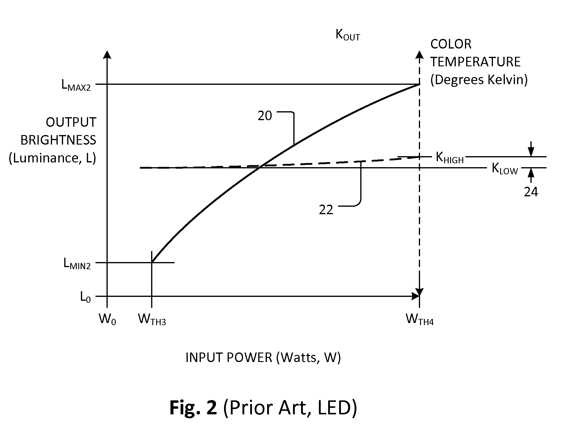
System and method providing LED emulation of incandescent bulb brightness and color response to varying power input and dimmer circuit therefor
a technology of led emulation and incandescent bulbs, which is applied in the direction of electroluminescent light sources, electric lighting sources, lighting and heating apparatus, etc., can solve the problems of significant changes in the color temperature of the light produced, discouraged use of incandescent lamps, and not good for the longevity of leds
- Summary
- Abstract
- Description
- Claims
- Application Information
AI Technical Summary
Benefits of technology
Problems solved by technology
Method used
Image

Examples
first embodiment
[0038]FIG. 3 illustrates a lighting system 500 in accordance with one embodiment of the present invention. Referring to FIG. 3, the lighting system 500 includes a first lighting module 530 and a second lighting module 540. The first lighting module 530 is adapted to connect to an alternating current (AC) electrical power source 120 via a dimming device 420. In the U.S., the AC power 120 provides a cyclical voltage of approximately 120 volts RMS (root mean square) with a peak voltage value ranging from approximately positive 170 volts (V) to approximately negative 170 volts. In Europe and other countries, the available AC power is approximately 240 volts RMS. Other countries may use a different frequency, for example, 50 Hz. Other platforms (for example, aircraft avionics) may use another frequency such as 400 Hz. The same principles apply to the following discussion regardless of applied oscillatory voltage or frequency. There are a number of dimmers in the marketplace that can be u...
second embodiment
[0070]The lighting system 500 of FIG. 3 may suffer from some level of undesired harmonic distortions because total current drawn by the system 500 from its input power source 420 may not represent a linear response to the sinusoidal shape of the input power. Total harmonic distortions (THD) and the techniques of reducing THD are disclosed in more detail in U.S. application Ser. No. 12 / 455,127, which has since issued as U.S. Pat. No. 8,354,800, the entirety of which both are incorporated herein by reference.
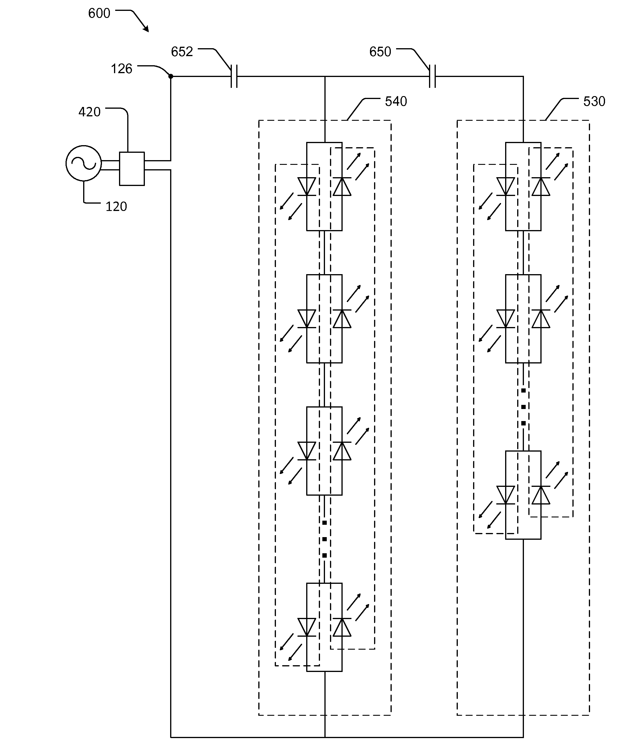
[0071]FIG. 6 illustrates a lighting system 600 in accordance with another embodiment of the present invention. Referring to FIG. 6, the lighting system 600 includes a first lighting module 530 and a second lighting module 540. The lighting modules 530 and 540 are configured similarly to those of FIG. 3 and discussed above. Other portions of the lighting system 600 that are similar to the lighting system 500 include the variable input power source 420.
[0072]In the lighting system 6...
third embodiment
[0082]FIG. 9 illustrates yet another embodiment of the present invention. Referring to FIG. 9, a lighting system 700 includes a first lighting module 730 including at least one light emitting element. In the illustrated embodiment, the first lighting module 730 includes a plurality of light emitting diodes serially connected in a forward direction. Again, the designation of forward or reverse is arbitrary. A first rectifier 732 is connected to the first lighting module 730. A first capacitor 650 is connected to the first rectifier 732. For the first lighting module 730, each light emitting element can be a light emitting diode (LED) such as, for example LED model LW540A which operate generally between three to four forward volts. LW540A and similar LEDs are available in the marketplace. In the illustrated embodiment, the first lighting module 730 includes 12 serially connected LEDs. The first rectifier 732 can have any known rectifier configuration. In the illustrated embodiment, th...
PUM
 Abstract
Description
Claims
Application Information