Method of measuring torque and torque measuring system for said method

a technology of torque and measuring system, which is applied in the direction of gearing, force/torque/work measurement apparatus, instruments, etc., can solve the problems of low reliability of bonding and high additional weight of balance mass and telemetry, limited lifetime, and high cost of structural modification of helicopters, so as to simplify the accessibility of components

Active Publication Date: 2014-11-18
AIRBUS HELICOPTERS DEUT GMBH
View PDF12 Cites 2 Cited by
  • Summary
  • Abstract
  • Description
  • Claims
  • Application Information

AI Technical Summary

Benefits of technology

[0017]The advantage of the inventive embodiment is especially that as a result of the arrangement of the vibration sensors outside of the turning drive shaft, it is no longer necessary to transmit signals from the turning body. Moreover, simplified accessibility of the components is enabled.

Problems solved by technology

Such a measurement system has the disadvantages of strain gauges with a limited lifetime, a low reliability of bonding and high additional weight of balance mass and telemetry.
For retrofit of said measurement system structural modifications of the helicopter are required with the implied high costs.
The telemetry system of said measurement system may cause electromagnetic interference with adjacent control units and thus may be at the origin of hazards and disturbances for the flight operation of such a helicopter.
The arrangement of specific magnetic layers is not always possible.
Said rotary shaft torque measuring system is complicated and bulky.

Method used


Image

  • Method of measuring torque and torque measuring system for said method
  • Method of measuring torque and torque measuring system for said method
  • Method of measuring torque and torque measuring system for said method

Examples


Embodiment Construction

[0023]To avoid repetition, in the following description and in the Figures, the same components are also identified with the same reference numbers if no further differentiation is necessary or useful.

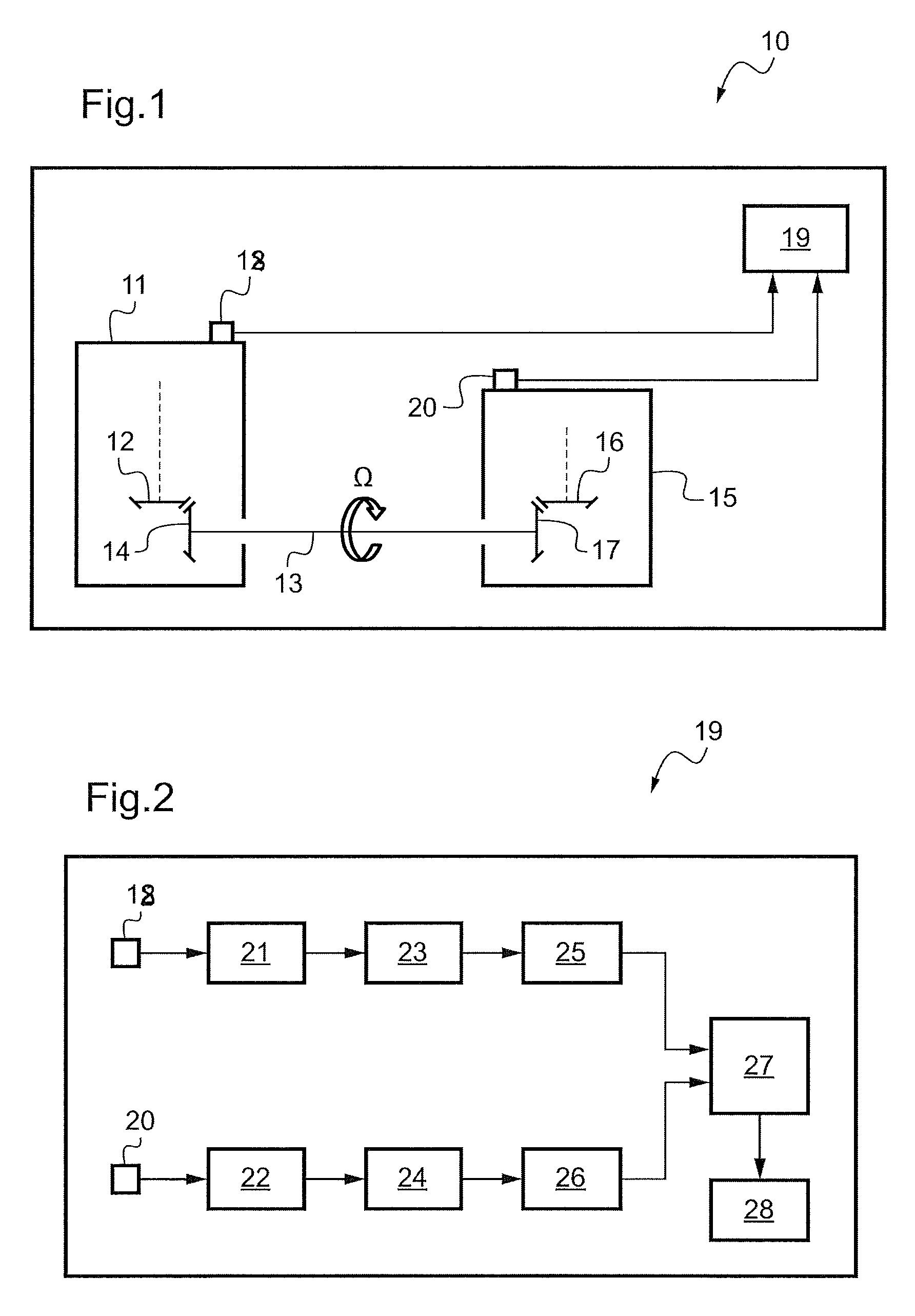
[0024]According to FIG. 1 elements of a schematically shown helicopter's drive system are labelled altogether with reference number 10. For reasons of clarity, an explicit description of the drive system is omitted here. Instead, the elements within the drive system correspond to those of known helicopter's drive systems.

[0025]A main gearbox 11 of the drive system comprises essentially a main gear in the form of a bevel shaped tail drive output gear 12 with a number of teeth z1. A drive shaft 13 is provided with a correspondingly bevel shaped first torque wheel 14 engaging fittingly the bevel shaped tail drive output gear 12 and extending through the main gearbox 11 towards a tail gearbox 15. The tail gearbox 15 comprises essentially a tail gear in the form of a bevel shaped aft input ...


PUM

PropertyMeasurementUnit
torqueaaaaaaaaaa
phaseaaaaaaaaaa
torsional stiffnessaaaaaaaaaa

Abstract

A method of measuring torque acting on a drive shaft (13) and a torque measurement system for implementing said method. Vibration sensors (18, 20) are attached to each of said main gearbox (11) and said tail gearbox (15) in order to detect gear mesh vibrations resulting from interaction of said drive shaft (13) with said main gear (12) and said tail gear (16), said detected gear mesh vibrations being transferred to an evaluation unit (19) for analysis.

Description

CROSS-REFERENCE TO RELATED APPLICATION[0001]This application claims the benefit of EP 10 400045.0 filed on Sep. 20, 2010, the disclosure of which is incorporated in its entirety by reference herein.BACKGROUND OF THE INVENTION[0002](1) Field of the Invention[0003]The invention relates to a method of measuring torque acting on a drive shaft and a torque measurement system for implementing said method. Although the method according to the invention and the measurement system according to the invention can fundamentally be used for a plurality of different applications, their use as a drive shaft torque measurement system, i.e., as a system for determining the torque or rotational moments acting on the tail rotor drive shaft of a helicopter, is presented in detail below. The term “tail gearbox” is to be understood as well as “intermediate gearbox”.[0004](2) Description of the Prior Art[0005]A tail rotor drive shaft between a main gearbox and a tail gearbox of a helicopter is submitted t...

Claims


Application Information

Patent Timeline
Patent Type & Authority Patents(United States)
IPC IPC(8): G01L1/00G01L3/00F16H61/00G01L5/00F16H3/38G01P3/48G01M13/02F16H59/00G01L3/10
CPCG01M13/028G01P3/48G01L3/109Y10T74/1926
Inventor DOLESCHEL, ANDREASWURZEL, GEORG
Owner AIRBUS HELICOPTERS DEUT GMBH
Why Eureka
Try Eureka