Method and device for dynamically resting roller segments that support and/or guide both sides of a cast bar made of metal, particularly steel

a technology of roller segments and continuous casting, which is applied in the direction of mould control devices, manufacturing tools,foundry moulding apparatus, etc., can solve the problems of no acceptance of other operations of methods, and achieve the effect of eliminating the bulging of the continuously cast strand and avoiding the damage of the roller segmen

Inactive Publication Date: 2010-12-07
SMS DEMAG AG
View PDF10 Cites 1 Cited by
  • Summary
  • Abstract
  • Description
  • Claims
  • Application Information

AI Technical Summary

Benefits of technology

[0003]The objective of the invention is to expand the previous objective, which was to develop an adjustment method that would avoid damage of the roller segments due to excessive forces and to eliminate bulging of the continuously cast strand as far as possible, by making the method accessible to a larger number of types of continuous casting operations.
[0004]In accordance with the invention, this objective is achieved by applying the method to roller segments of continuous bloom and billet casting machines, such that the roller segments are installed in the cold bar zone, the hot bar zone, and / or the soft reduction zone. This allows gentle adjustment of roller segments that is adapted to the given type of operation, even in the case of continuously cast bloom and billet cross sections.
[0009]In accordance with other features of the invention, the drives for the driven rollers are designed in such a way that the drive motor for a driven roller is arranged, together with a transfer case, on one side of the segment frame with a vertical drive shaft orientation. In this way the power transmission is direct, and the accessibility of the motors is advantageously simple.

Problems solved by technology

However, the method found no acceptance in other operations, except for slab and thin-slab continuous casting machines.

Method used


Image

  • Method and device for dynamically resting roller segments that support and/or guide both sides of a cast bar made of metal, particularly steel
  • Method and device for dynamically resting roller segments that support and/or guide both sides of a cast bar made of metal, particularly steel
  • Method and device for dynamically resting roller segments that support and/or guide both sides of a cast bar made of metal, particularly steel

Examples


Embodiment Construction

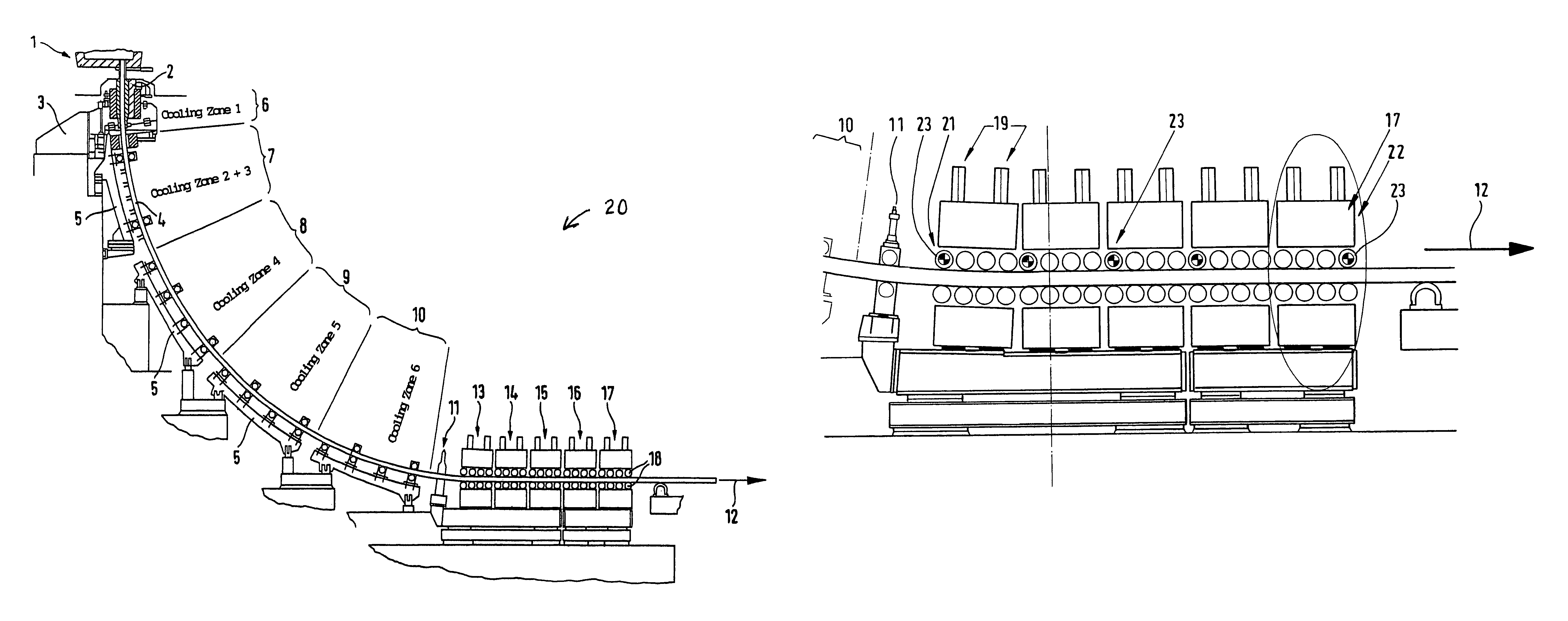
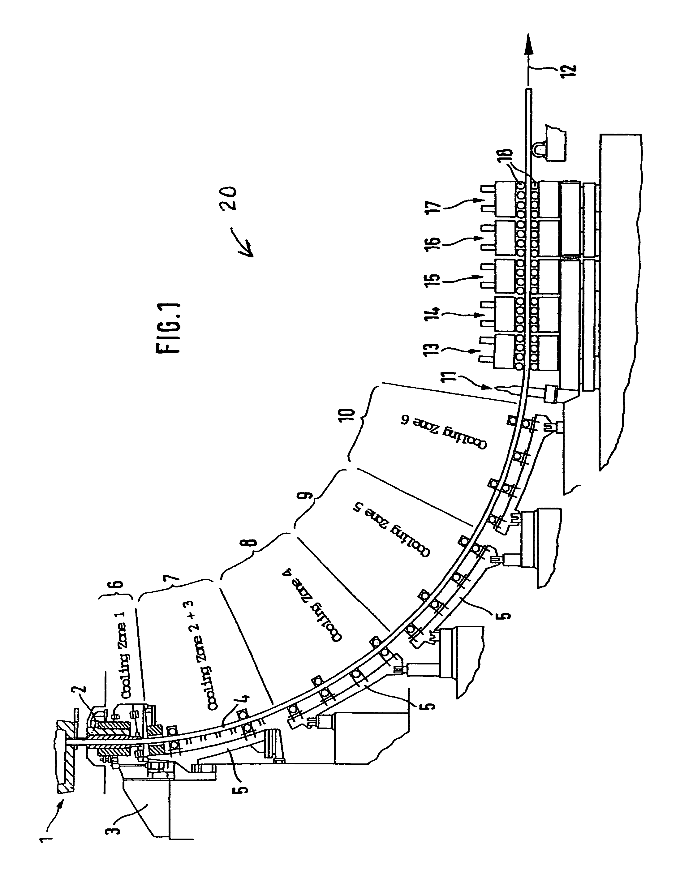
[0022]Molten steel flows from a tundish 1 into a cooled continuous casting mold 2, which is oscillated by an oscillation unit 3 to produce shell solidification of the continuously cast strand 4 leaving the continuous casting mold 2 and prevent sticking. The continuously cast strand 4, which is liquid on the inside and is guided in containment roll stands 5 passes in succession through cooling zones 6, 7, 8, 9, and 10 and then enters a bending-straightening unit 11. Moving in the direction of strand movement 12, the continuously cast strand 4, which has now cooled further, enters roller segments 13, 14, 15, 16, and 17 (FIG. 1).

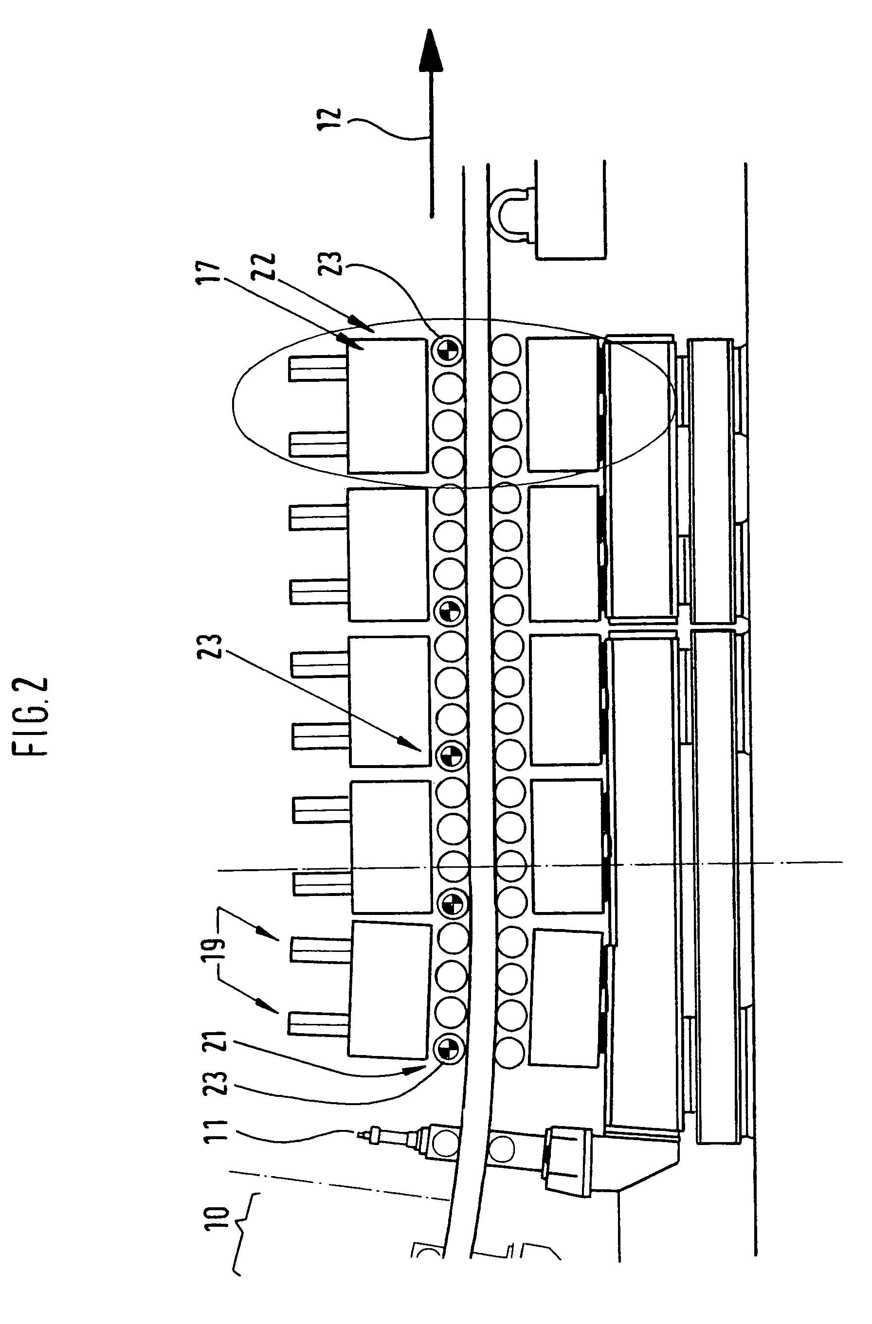
[0023]Each roller segment 13 to 17 has at least two pairs of rollers 18. Each roller segment 13 to 17 is equipped with a pair of piston-cylinder units 19, which, however, are successively arranged on a center line within a roller segment 13 to 17 and adjust only an upper part of the corresponding roller segment, while the lower part is rigidly mounted on the se...


PUM

PropertyMeasurementUnit
pressureaaaaaaaaaa
hydraulic pressureaaaaaaaaaa
distanceaaaaaaaaaa

Abstract

A method and continuous casting device for dynamically placing rolling segments against a cast bar made of metal, particularly steel. The continuous casting device is a bloom or billet casting device and has pairs of rollers that are placed against each other in a position-controlled and pressure-controlled manner by piston-cylinder units. The hydraulic pressure is switched from position-controlled operation to pressure-controlled operation when a threshold pressure is reached. The roller segments are arranged in the hot bar zone and the soft reduction zone.

Description

BACKGROUND OF THE INVENTION[0001]The invention concerns a method and a continuous casting device for the dynamic adjustment of roller segments that support and / or guide both sides of a continuously cast strand made of metal, especially steel, with at least two successive pairs of rollers, which are adjusted relative to each other by piston-cylinder units, which are acted upon with both position control and pressure control, and the pairs of rollers are then adjusted to the continuously cast strand by position control, and the hydraulic pressure is switched from position-controlled operation to pressure-controlled operation when the hydraulic pressure in a piston-cylinder unit reaches a predetermined value.[0002]A method of this type a described in EP 1 062 066 B1. The method was previously used on driver stands of bloom and billet continuous casting machines, in which the hydraulic piston-cylinder units are position-controlled and pressure-controlled. However, the method found no ac...

Claims


Application Information

Patent Timeline
Patent Type & Authority Patents(United States)
IPC IPC(8): B22D11/128B22D11/20B22D11/12
CPCB22D11/1206B22D11/208B22D11/12
Inventor ZAJBER, ADOLF-GUSTAVBEYER-STEINHAUSER, HOLGERGEERKENS, CHRISTIANWEYER, AXEL
Owner SMS DEMAG AG
Why Eureka
Try Eureka