
Knife and counter knife in machine disk

a technology of cutting disc and knife, which is applied in the direction of mowers, agriculture tools and machines, and mowers, etc., can solve the problems of inability to replace the blade, inability to reduce the cutting edge of conventional hardened steel blades, so as to reduce the downtime of the sugar cane cutting machine , the effect of fast replacement of the knife s

Inactive Publication Date: 2014-11-25
OREGON TOOL INC
View PDF41 Cites 21 Cited by
  • Summary
  • Abstract
  • Description
  • Claims
  • Application Information

AI Technical Summary

Benefits of technology

This configuration significantly reduces downtime, lowers production costs, and improves cutting performance by allowing faster and more efficient blade replacement, using less steel and reducing machine power consumption.

Problems solved by technology

However, due to the intense cutting activity executed closely to the ground, conventional blades manufactured with hardened steel quickly experience considerable wear on the cutting edges.
This wear forces the machine operator to make constant replacements of the blades.
Replacement of the knives results in undesirable machine shutdown because each knife is fixed on the rotating disc by two bolts.
This replacement process usually happens in unfavorable locations, i.e., in the cane field, with poor lighting because of the position of the operator.
It should be emphasized that during these knife replacements, the bolts used to secure the knives to the rotating disc are often lost in the vegetation.
Because of these inconveniences, the blade replacements cause machine shutdowns and end up reducing the productivity of sugar cane cutting operation.
This single-piece design is a non-economical feature because short term replacements are inevitable due to wear of the cutting edges.
These replacements result in an increased cost of the sugar cane cutting operation.

Method used


Image

  • Knife and counter knife in machine disk
  • Knife and counter knife in machine disk
  • Knife and counter knife in machine disk

Examples


first embodiment

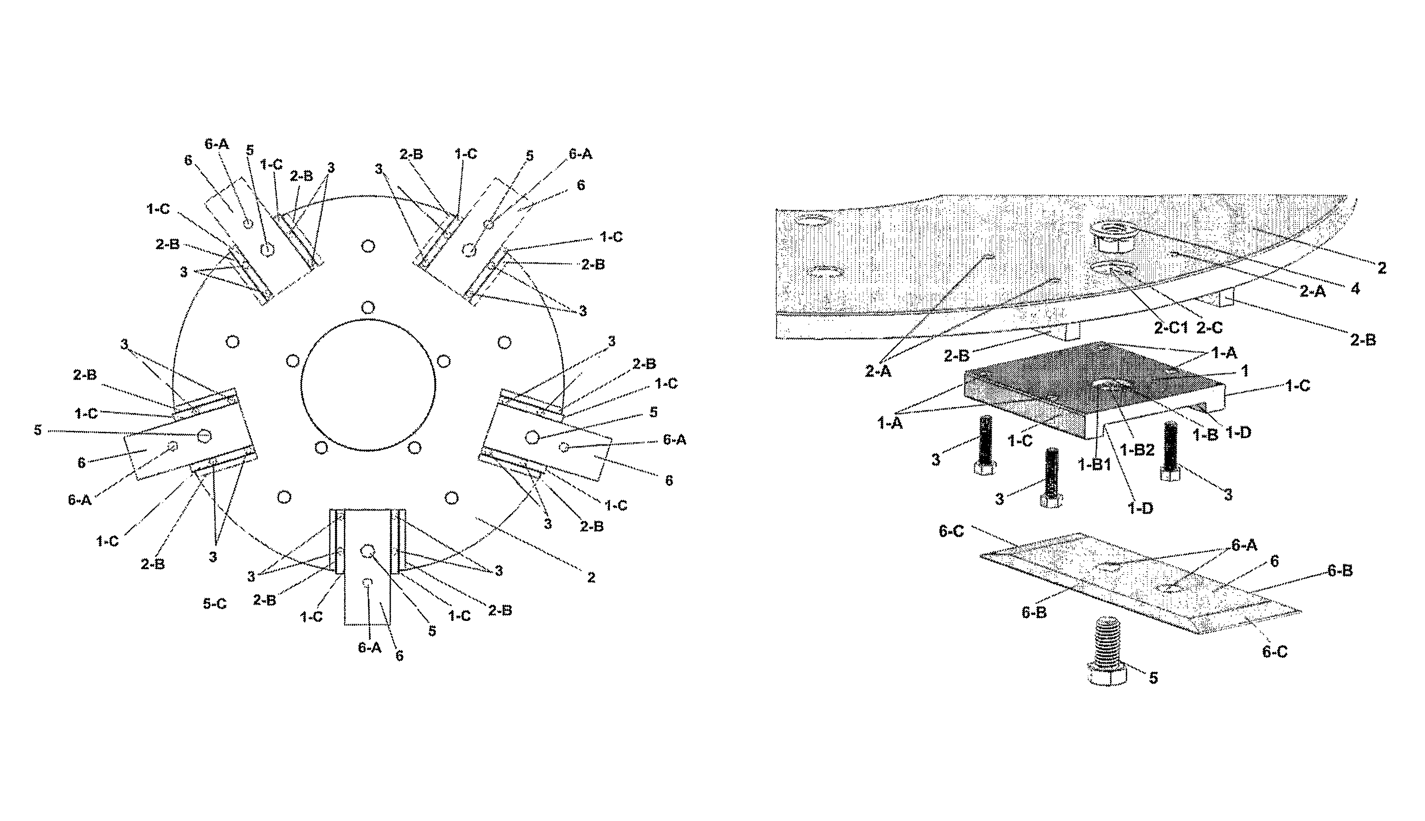
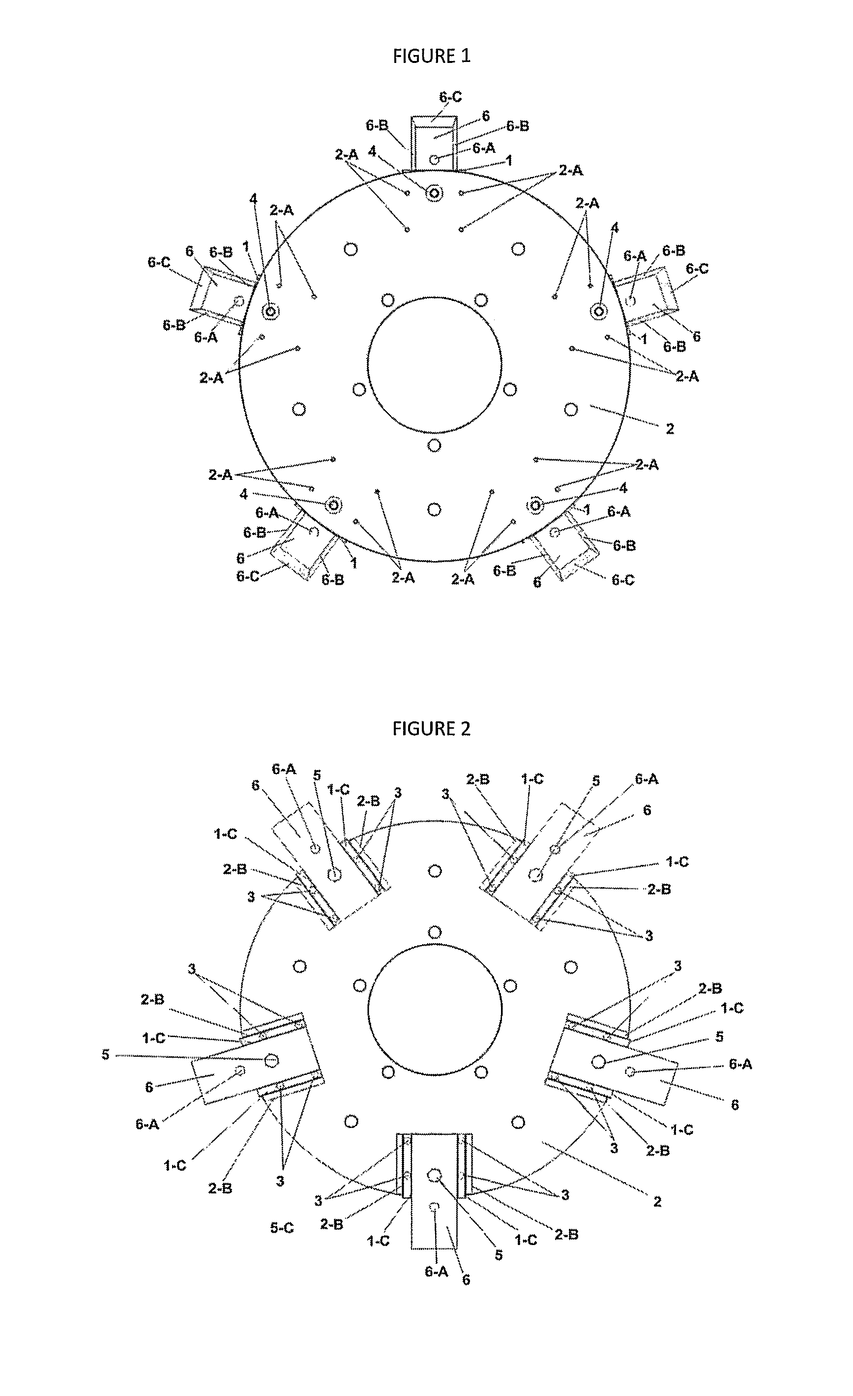
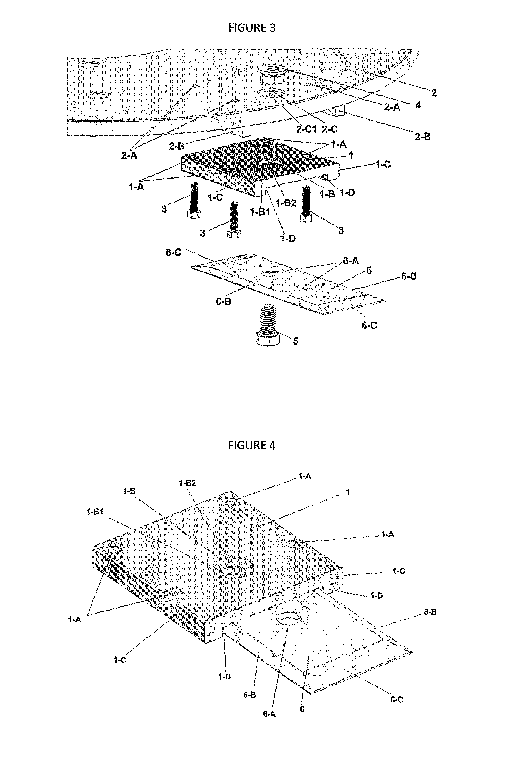
[0016]FIGS. 1 to 4 show the knife and counter knife set containing a rectangular counter knife (1) with four holes (1-A) formed symmetrically in the upper surface. Two holes (1-A) are positioned along one side of the counter knife (1) and the other two holes are positioned along the opposite side of the counter knife. The counter knife (1) includes a larger diameter hole (1-B) transversally centralized and longitudinally decentralized, that has a circular inner recess (1-B) forming a hole with smaller diameter (1-B2). The counter knife (1) further includes two lateral, longitudinal, parallel, rectangular and vertical walls (1-C) inferiorly forming a rectangular recess or cradle (1-D).

[0017]The counter knife (1) is fixed on rotating disc (2) through hex-head bolts (3) on by-pass holes (1-A) which are adjusted in four holes in the inferior-superior direction (2-A) on the disc surface (2), matching the four holes (1-A). The two rectangular, inferior and transversal guides (2-B) of the ...

second embodiment

[0018]FIGS. 5 to 8 show the knife and counter knife set, containing a rectangular knife (7) with a longitudinal, central and oblong opening (7-A). The opening (7-A) has two central, opposite and semi-circular projections (7-A1) that form a central circular opening in the middle of the knife. The knife (7) further has two side cutting edges (7-B) and two end cutting edges (7-C).


PUM


Abstract

A rectangular counter knife with a larger diameter hole, the counter knife has two lateral, longitudinal, parallel, rectangular and vertical walls inferiorly forming a rectangular recess, the two rectangular, inferior and transversal guides of the rotating disk, support the rectangular knife, adjusting a hex-nut in a larger diameter hole, coincident to the hole, receiving these holes on inferior-superior direction, a hex-head screw initially by-pass one of the two holes centralized along one rectangular knife with two side cutting edges and their ends have, a constructive variant comprising a rectangular knife with a longitudinal, central and oblong opening, with two central, opposite and semi-circular projections forming a circular central opening in the middle of the knife; the rectangular knife has two side cutting edges and two cutting edges on the ends.

Description

CROSS REFERENCE TO RELATED APPLICATIONS[0001]The present application claims priority to PCT Application No. PCT / BR2010 / 000184, filed Jun. 1, 2010, entitled “Knife and Counter Knife in Machine Disk,” which claims priority to Brazilian Utility Model Application No. MU 8901415-4 filed Jun. 9, 2009, the entire disclosures of which are hereby incorporated by reference in their entirety.TECHNICAL FIELD[0002]The present patent refers to a utility model of a rotating cutting disc, a counter knife, and a knife of a sugar cane harvesting machine. The counter knife and knife allow the increase of speed in the cut of sugar cane and economy in manufacturing of the cutting components.BACKGROUND[0003]As is known among sugar cane producers, sugar cane harvesting machines are currently equipped with rotating discs that have coupled to their circumference steel knives which are responsible for cutting the sugar cane. However, due to the intense cutting activity executed closely to the ground, convent...

Claims


Application Information

Patent Timeline
Patent Type & Authority Patents(United States)
IPC IPC(8): A01D34/73A01D45/10A01D34/52
CPCA01D45/10A01D34/733
Inventor NIKKEL, WALTER
Owner OREGON TOOL INC
Learn More